Installation and Maintenance Manual
41
(-) (-)
(+)
PIN
2
PIN
1
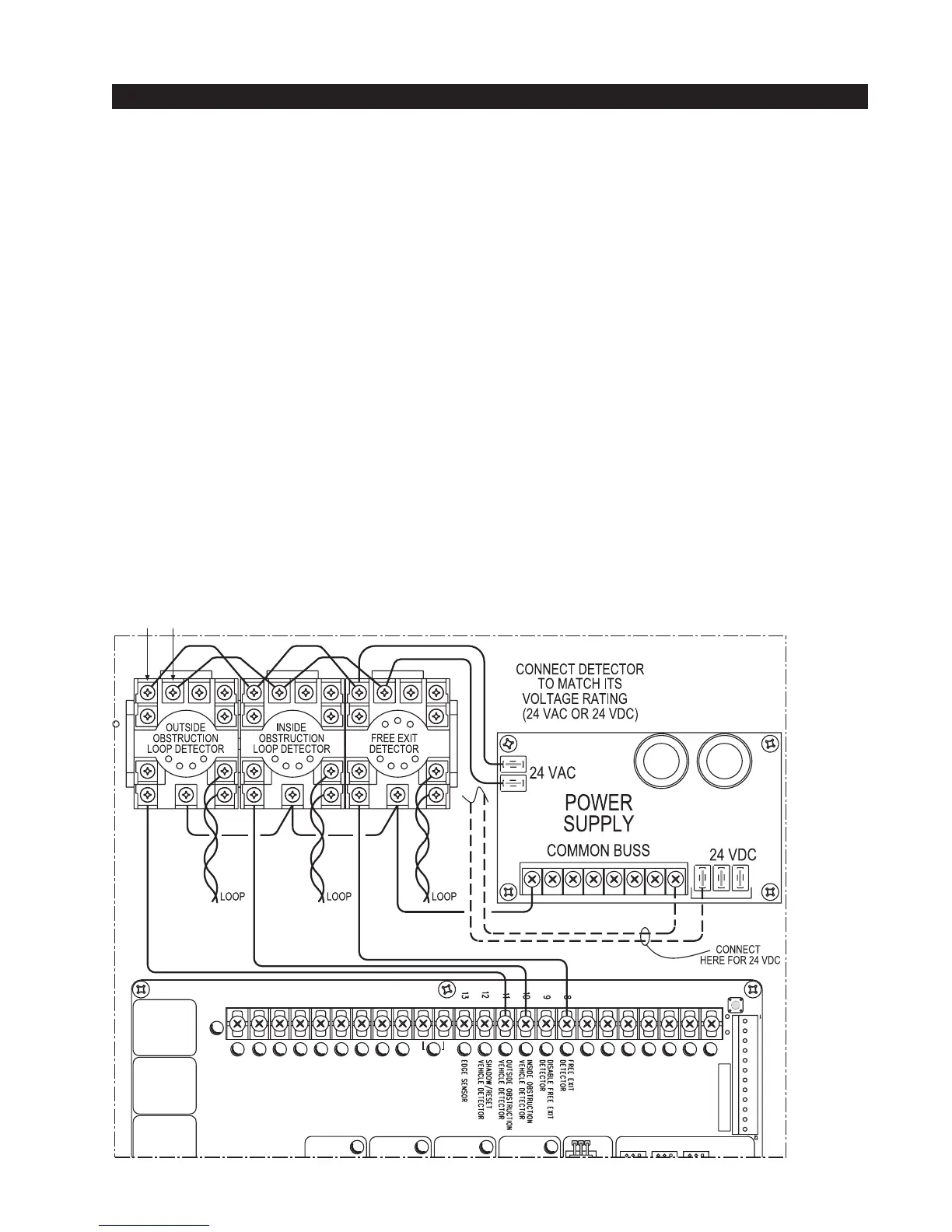
Standard 11 Pin Box Type Vehicle Detector Installation
1. If standard 11 pin vehicle detectors are to be used, snap up to three sockets onto the aluminum DIN
mounting rail, with the key in the center hole facing to the left.
2. Both 24 Volts AC or DC are available, so either detector voltage may be used. (24 VAC is not available
if the operator is a battery type) 24 VAC is available at the spade terminals on the lower left corner of
our power supply (marked ACC). 24 VDC is available from the Common Buss and the +24 V spade
terminals next to the common Buss.
3. Connect 24 Volt power to the detector. Polarity does not matter if the detector is a 24 AC model. If a
DC detector is used, pin #1 is (+) on a DC detector and pin #2 is ( - ).
4. Connect the output pin #6 to the common Buss on the power supply and the output pin #5 to one of the
four detector inputs (depending upon the detector function required) on the Smart Touch Controller
terminal strip.
5. If multiple detectors are used, join the wires from socket to socket rather than run each to the same
location separately. The only wire that must be separate is the output wire to the Smart Touch Control-
ler as well as the loop input wires.
6. Always keep the loop wires well twisted at all places beyond the area of the loop. The lead in portion
sealed in a saw cut does not need to be twisted so long as the wires are encapsulated in loop sealant
and cannot move.