Installation and Maintenance Manual
54
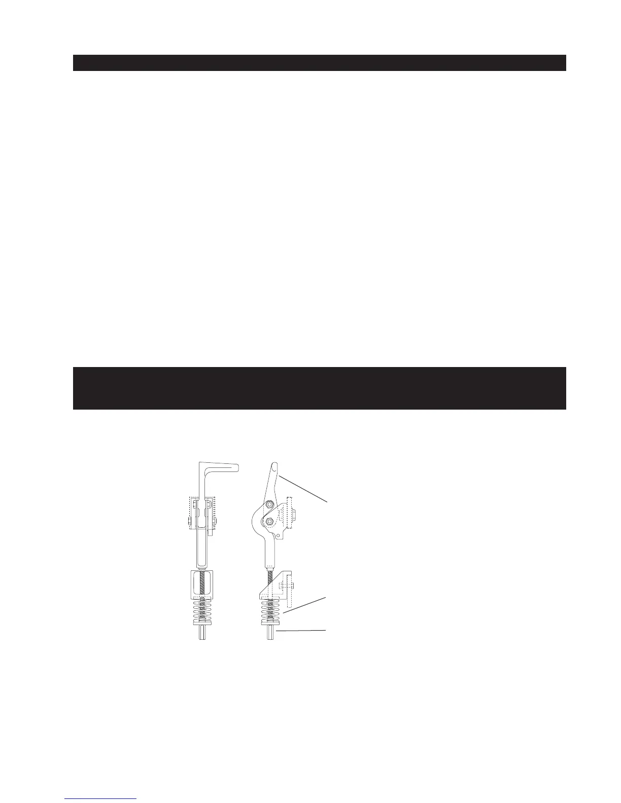
Manual Release Handle
Red Spring Controls
Wheel Grip
Coupling Nut for Spring
Tension Adjustment
Use and Adjustment of the Manual Release Mechanism
All slide gate series operators come equipped with a toggle handle manual release mechanism to
disengage the drive wheels from the drive rail. The manual release is located under the electric
control panel and to the right of the hydraulic motors. To disengage the drive wheels, simply pull the
aluminum handle down.
USE CAUTION: at first the toggle handle will rapidly pop down, as the loaded spring releases. This
action will cause the lower drive wheel to drop and disengage from the drive rail. When the coupling
nut on the threaded rod drops to its lowest position it will push on the base of the operator which will
cause the upper drive wheel to lift and disengage from the drive rail.
For shipment, a piece of wood was placed between the coupling nut and the chassis. If the wood is
still in place, discard it.
If the drive rail has been installed at the correct height to the chassis, the manual toggle release
mechanism will equally spread both wheels away from the drive rail. If the rail has been mounted
higher than specified, it may be necessary to insert a 3/8" bolt into the bottom of the coupling nut
which will create additional lift clearance for the upper drive wheel when manually released. If used,
adjust the 3/8" bolt so the drive wheels spread equally when the manual toggle release is fully
disengaged.
The coupling nut must always be adjusted correctly so the wheels provide a strong clamp-
ing force on the drive rail. The red spring should measure 2" to 2-1/8" in height when
under correct compression.