Installation and Maintenance Manual
33
Installing Gate Edge (Contact Type) Reversing Sensor
1. Follow the guidelines in the Entrapment Protection Schematic to plan the most appropriate mount-
ing positions for the edge sensors to be installed. For sliding gates, one or more sensors shall be
located at the leading edge, trailing edge and post mounted both inside and outside of a sliding gate.
A requirement of the UL 325 standard is that an edge sensor be laboratory tested and “recognized”
under UL 325.
2. Drill holes through the edge’s mounting channel and through the surface that each gate edge is to
be mounted. Securely fasten every edge sensor. The edge sensors should all be placed not higher
than 6" above the ground.
3. Edge sensors that are not attached to the moving gate, such as post mounted sensors are wired in
parallel and directly connected to the gate operator:
a. Mount a gate edge to the wall, pilaster or end post of the fence that aligns with the gate when it is
in the open position.
b. Always route the leads of the edge sensors to the gate operator so that they are protected from
physical damage.
c. Connect one edge sensor lead to our Common Buss on the power supply board and the other to
terminal #13, which is labeled Edge Sensor input.
4. Edge sensors mounted to the leading edge or trailing edge of the gate panel should be used with an
edge transmitter and a receiver in order to transmit to the gate operator. We do not recommend the
use of retractable cord reels or curl cords because of durability problems with these devices in outdoor
environments.
a. Mount gate edge sensors to the leading edge and trailing edge of the gate so that entrapment
protection is provided in both directions of travel.
b. Mount one or two edge transmitters (Linear Model #3022 or equivalent) onto the gate panel near
the upper corner of the leading edge of the gate. Both gate edges will function correctly if only
one transmitter is used, but wiring both edges to a single transmitter may be impractical or
displeasing visually.
c. Connect the edge(s) to the terminals in the edge transmitter and set the DIP switches of the
transmitter to match the setting in the receiver to be used.
5. Mount a commercial style radio receiver* (external antenna type) on the inside of the operator,
below the electrical box. Knock out the smallest hole in the lower right corner of the electrical box and
route the wires to the area marked Radio Options. Only three wire connections are needed because
the 24-Volt supply and the radio output share a wire. Being certain to observe polarity, crimp the black
radio power wire together with one of the radio output wires into a .25" spade connector and connect
to the COM terminal. Connect the red wire to the +24V terminal and connect the other radio output
contact wire to the spade marked EDGE. Note that this terminal is the same as the #13 input terminal
labeled Edge Sensor on the main control board.
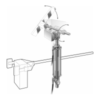
a. Mount an external antenna onto the top of a fixed post of the fence near the operator.
b. Connect the antenna into the socket on the radio receiver.
c. Set the DIP switches in the receiver to match the same code used in the transmitter.
6. Test the operation of the reversing edge to make sure that it is functions correctly. Advise the user of
the gate to be certain to retest this vital function weekly.
* If there is also to be a radio receiver for a hand held transmitter to operate the gate, be certain to
use a two channel commercial receiver. Remember that the transmitter and receiver must have
their codes set the same or they will not function.