Installation and Maintenance Manual
46
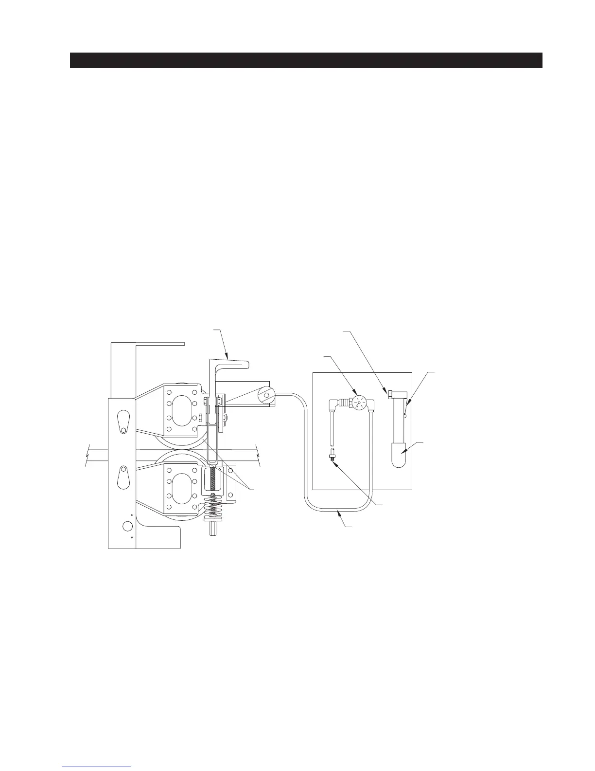
DRIVE
WHEELS
PUMP LEVER
HAND PUMP
THREADED COUPLING
FLEXIBLE PLASTIC AIR HOSE:
CONNECT TO WHEEL CLAMP MECHANISM
WHEEL CLAMP LEVER
INSERT THREADED
COUPLING HERE
GUAGE
Remote Release Mechanism
(Model #A MILR 001 R or A MILR 001 RCF)
Instructions for Releasing Drive Wheel Clamp Mechanism for Manual Operation
This remote release device consists of an air cylinder inside the operator, which pushes the wheel
clamping device open, a length of flexible air tubing, and a remote box containing a hand pump.
The hand pump is just like the ones used to inflate sports equipment or bicycle tires.
1. Remove hand pump from box. (Pull straight out to remove from mounting clips.)
2. Push threaded coupling, attached to end of tubing, into hand pump. Do not screw or twist.
3. Lock coupling in place by toggling the locking lever away from pump.
4. Pump until gauge pressure indicates 50 PSI. The clamp on the wheel should now be released and the
gate can be manually operated. Do not release pressure until all manual operations are complete.
5. When ready for automatic operation, release fitting from pump by lowering lever and pulling tubing
straight out. This will release the pressure on the wheel clamp mechanism.
6. Put pump and tubing back into enclosure.
7. Re-engage the release mechanism inside the gate operator housing.