Power Plasma
Supply CNC Interface
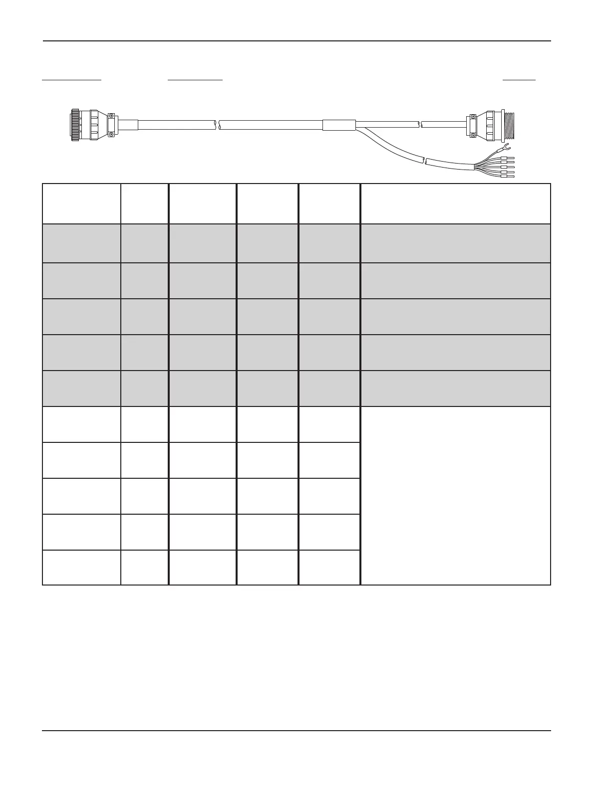
Signal Name Color End (1X1) End End Function
Hold I/O – Black 1 Not J4-6 (Optional) Hold Ignition (I/O) signal used for preflow
Hold I/O + Red 5 Connected J4-5 during IHS. Also used by power unit to synchronize
Drain Drain 10 operation of multiple torch installations.
Pierce Complete + Black 2 Not J4-8 (Optional) Pierce Complete signal used by power
Pierce Complete – White 6 Connected J4-7 unit to time transition from pierce gas flow to cut gas
Drain Drain 11 flow. User enters this time delay into THC.
Pilot Arc Out + Black 3 Not J3-4 (Optional) Pilot Arc Out signal. Maintained during
Pilot Arc Out – Green 7 Connected J3-3 torch ignition. Contact closes after torch ignition. Dry
Drain Drain 12 contact closure.
Plasma Start – Black 9 Not J4-4 Plasma On signal maintained during plasma cut. If
Plasma Start + Yellow 15 Connected J4-3 signal is lost, system must be restarted.
Drain Drain 14
Transfer Out + Black 37 Not J3-2 Arc Transfer signal. Contact closes after arc transfer
Transfer Out – Orange 32 Connected J3-1 and pierce delay (set on power supply front panel).
Drain Drain 26 Dry contact closure.
Power Off Black 4 4 Not
Power Off Blue 8 8 Connected
Drain Drain 13 13
External Interlock Red 16 16 Not
External Interlock Blue 17 17 Connected
Drain Drain 18 18
Power On Input Black 29 29 Not These signals connect to the CNC. Refer to HD3070
Power On Input Brown 34 34 Connected Instruction manual for signal information.
Drain Drain 23 23
Power Interlocks Red 35 35 Not
Power Interlocks White 30 30 Connected
Drain Drain 24 24
1/50 AC Volts Red 33 33 Not
1/50 AC Volt Green 28 28 Connected
Drain Drain 37 37
HD3070 SETUP
3a-6 CommandTHC for X-Y Table Instruction Manual
9
Figure 3a-3 HD3070 interface cable – part number and signal list
Part number Description Length
123270 HD3070 Power Supply Interface Cable 6 ft./1.8 m
Shaded area indicates plasma interface assembly connections.
Plasma interface assembly other J3 and J4 connection points:
• J3-5 (+) and J3-6 (–) – Alternate Nozzle Contact. An optically isolated signal that indicates nozzle is in ohmic contact with work.
Ohmic contact is represented by a logic 1.
• J3-7 through J3-12 – Reserved for future use.
• J3-13 and J3-14 – Protective earth ground.
• J4-1 (+) and J4-2 (–) – Available 24 VDC, 500 mA maximum
• J4-9 through J4-12 – Reserved for future use.