www.hysecurity.com © 2019 General Maintenance MX3630-01 Rev. J 125
Drive Wheel Spring Tension (Adjustment of Manual Release)
All SlideDriver operators come equipped with a toggle handle manual release mechanism to disengage the
drive wheels from the drive rail.
During shipment, a piece of Styrofoam is placed between the coupling nut and the chassis. If the packaging is
still in place, discard it.
When releasing the handle inside the chassis, be careful as the mechanism is spring-loaded and drops rapidly.
Hold the toggle handle appropriately so your ngers do not get pinched, hit, or crushed.
To disengage the drive wheels, simply pull the aluminum toggle handle down. As the lower drive wheel
drops and disengages from the drive rail, it causes the coupling nut on the threaded rod to drop to its lowest
position and push on the base of the operator. This causes the upper drive wheel to lift and disengage from
the drive rail.
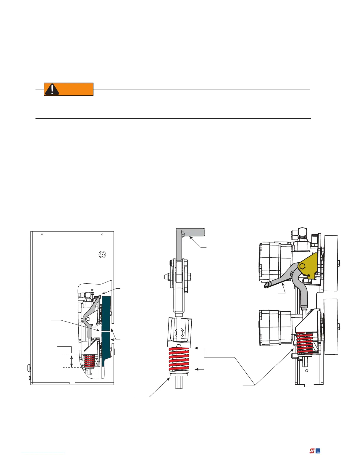
The coupling nut must be adjusted correctly so the wheels provide a strong clamping force on the drive rail.
The red spring should measure 2 to 2-inch (5 to 5.5cm) in height when under the correct compression.
NOTE: If the drive rail is installed at the correct height to the chassis, the toggle release mechanism spreads both wheels equally in
relation to the drive rail. If the drive rail has been mounted higher than specied, it may be necessary to use an additional coupling
nut and ” bolt which can extend beyond the all thread and create additional lift clearance for the upper drive wheel when the
toggle handle is released. If this extension method is used, adjust the ” bolt so the drive wheels spread equally when they are
fully disengaged.
2 to 2”
(5 to 5.4 cm)
Toggle handle
clamped
(Load
position)
Coupling Nut:
Adjusts compression spring.
Toggle handle
Drive wheels
Drive rail slides
between drive
wheels
Toggle Handle
unclamped
Compression Spring:
Controls drive wheel gripping force. Set
at 2 in. (5 cm) when Drive Wheels are
clamped on the Drive Rail. Toggle handle
is in the clamped (load) position.