www.hysecurity.com © 2019 STC Inputs & Wiring MX3630-01 Rev. J 71
Smart Touch Controller Inputs
When using AC power, an LED lights next to any active input.
1. Test the open and close function of the gate before wiring to accessory devices (external control
inputs). This makes it easier to troubleshoot if an unexpected functionality arises.
NOTE: If you are using the operator strictly in a DC capacity, the Smart Touch Controller has a tact button you
can push which lights an LED next to the active inputs. This button is in the bottom left corner of the STC board.
Press the SHOW LEDs push button switch to verify the status of the terminal inputs.
2. All the Smart Touch Controller inputs listed below are shown as a single input. The second wire is
connected to the Common Terminal Bus on the Power Supply Board.
NOTE: The Emergency Close and Fire Dept. Open inputs are an exception and require a +24V input.
The +24V is located on Power Supply Board next to the Common Bus. See illustration on previous page.
STC Terminal Inputs
WARNING
Use Terminal Inputs 4, 5, 6, and 7 for external control devices. DO NOT connect an external control device to
Input Terminals, 1, 2, or 3 unless the controls are located in clear view of the entire gate area and are being
constantly monitored and supervised.
NOTE: UL 325 2016 sensor input label changes shown in Bold.
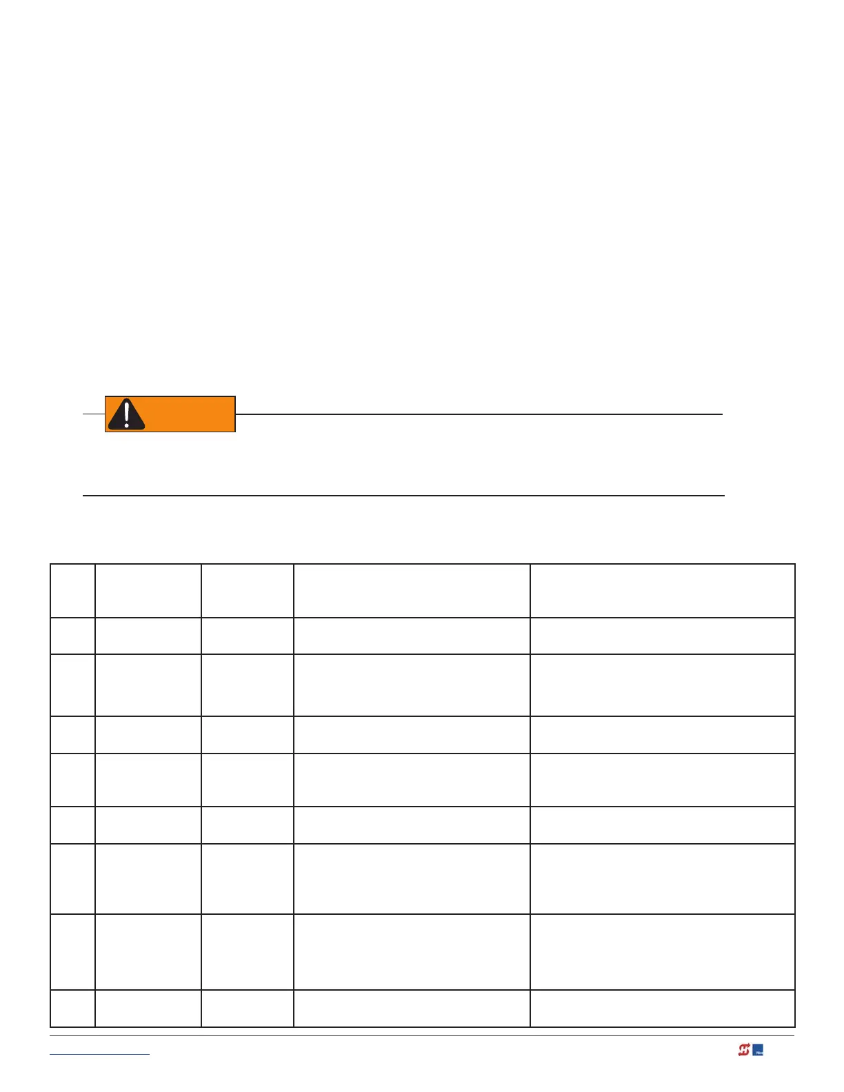
Smart Touch Controller Inputs Chart
No. Smart Touch
Terminal
UL 325 - 2016
Smart Touch
Terminal
pre-2016
Wire Connections Commonly used for...
1 Stop Button Stop Button Normally Closed input. Jumper to
Common if input is not being used.
Line of sight, external stop button or 3-button
station.
2 Open Button Open Button Do not use for radio or remote access
controls.
Normally Open Input
Line of sight, external open button or
3-button station.
3 Close Button Close Button N.O. input. Connection for a close push-
button.
Line of sight, external close button or
3-button station.
4 Remote Open &
Radio Control
Remote Open
& Radio
Control
N.O. input. For radio/remote open
device - Program to also Close in User
Menu (RO 1).
Remote access control or radio controls
5 Open/Close
Button
Open/Close
Button
Connection for push button or radio
controls.
Singular button device (multi-function)
6 Open Partial Open Partial N.O. input. This input will cause the gate
to open to the Partial Open position
programmed in the Installer Menu (7-
32ft).
Supervised access controls
7 Interlock Open/
Time Clock
Open LED
Interlock
Open/Time
Clock Open
LED
The default is Interlock Open (TC 1) but
can be congured as the Time Clock
Open
(TC 0) input.
When set to TC1, terminal acts as sequenced
or interlocked gate input. Set to TC0, this
input provides a connection to a device that
regulates the open timing.
8 Free Exit Vehicle
Detector
Free Exit
Vehicle
N.O. input. Free Exit Vehicle Detector
connection.
Vehicle detector, box type connections for
free exit loop.