28 MX3630-01 Rev. J SlideDriver/SlideDriver 50VF Series © 2019 www.hysecurity.com
Initial Setup
When you rst apply power to the gate operator, it is locked in Menu mode
and prompts appear on the display. The gate will not move and the controls
will not function until the prompts have been answered. The prompts
include:
• Usage Class setting
• Gate handing
• Three external entrapment protection SENSOR assignments
Before turning the power switch to ON, be sure to replace the vent cap with the
breather cap. See page 30. Make sure all site requirements concerning proper
wiring, safety, foundation installation, and electrical power have been met.
Five buttons on the display keypad provide operational controls. Refer to
Display & Menu Options on page 50 for more information. To answer the
initial prompts, use the Previous, Next, and Select buttons as described in
the chart below:
Smart Touch Controller: Menu Mode Navigation Buttons
To change that data
appearing in the display
To navigate through the
Selections
To choose what appears on
the display
To navigate between
menu items
Press Select.
Two left characters blink.
Press Next.
Continue pressing Next to view
all selections. (Press Previous to
reverse direction.)
Press Select.
Blinking characters
become static.
Press Next or Previous.
Advance - press Next
Previous - press Previous
If you are unsure of the usage classication, refer to page 11. It explains the different usage site
classications for UL 325.
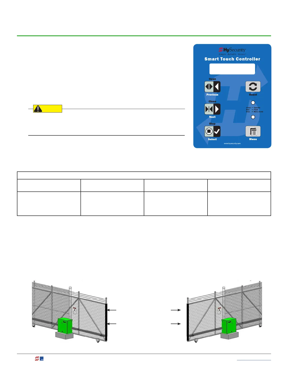
Gate Handing
The handing is determined by the position of the operator and which way the gate opens. To determine
handing, face the front cover panel on the operator. All SlideDrivers ave the hoses congured at the factory for
right handing. If the gate has left handing, the hydraulic hoses must be swapped. See page 29.
UC 2
USAGE CLASS
OPEN OPEN
Left-Hand
Gate
Right-Hand
Gate