www.hysecurity.com © 2019 Entrapment Protection MX3630-01 Rev. J 37
After programming the sensor inputs in the installer menu or during initial startup, the appropriate type and
number of sensors will need to be connected. Figure below shows the wiring and dip switch settings of an
EMX-MON photo eye (typical thru-beam wiring). A retroreective photo eye will be similar and only have
wiring simliar to the receiver of the thru-beam photo eye.
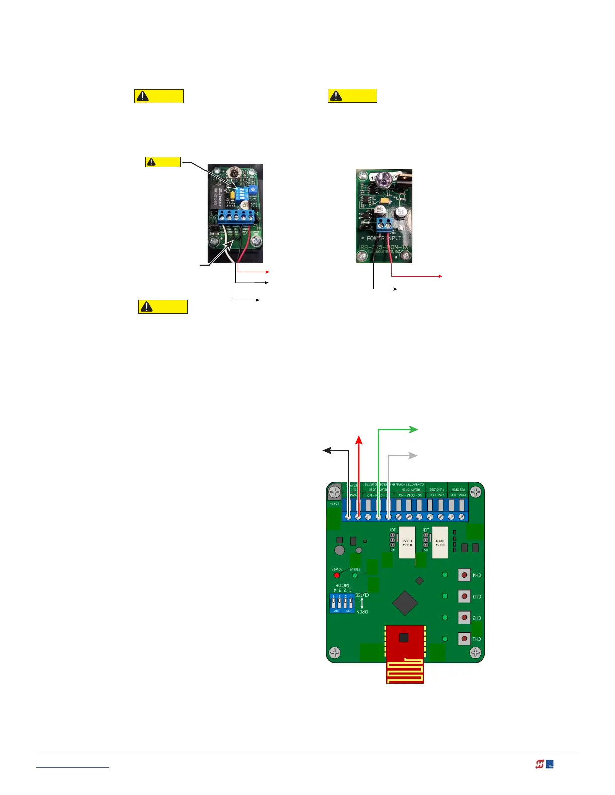
An Edge Sensor can be either hardwired through an adapter module (Hy2NC) or a wireless transmitter receiver
combo (WEL-200 or iGAZE RE). Figure below shows the wiring and dip switch settings of a WEL-200. For more
information and wiring diagrams of other recommended sensors see the “HySecurity External Entrapment
Sensor Wiring Guide”.
EMX IRB MON
Photo Eye
Receiver
All external entrapment protection sensors must be
NC sensor outputs and wired to the SENSOR COM
terminal for monitoring and powering purposes.
The sensor becomes actively powered when the
gate operator's motor runs.
CAUTION
Connect all contact and non-contact sensors to same power
source. Example, Do NOT connect photo eyes to +24VDC
and gate edges to +12VDC. Incompatible electricity flow. A
FAULT 2 will appear.
CAUTION
EMX IRB MON
Photo Eye
Transmitter
CAUTION
Set DIP
Switches
1 = OFF
2 = OFF
3 = OFF
4 = ON
NOTE: DIP switches
mustbe set as shown
otherwise the photo
eye will not operate
correctly.
Jumper POWER INPUT
- 24V to COM in Receiver
COMMON / NEG. to SENSOR COM
RED
NC RELAY to SENSOR 1
+24V
COMMON / NEG. to SENSOR COM
RED
+24V
BLACK
WHITE
BLACK
DIP switches must be set as shown otherwise the photo eye will not operate correctly. If you receive an Alert,
"!ACTION BLOCKED" "Photo Eye Open" PEO or "Photo Eye Close" PEC, take steps to align the photo eye.
CAUTION
SENSOR 1,2, or 3
SENSOR COM
SENSOR COM
+24V
EMX WEL-200 Wireless Edge Receiver
Dip Switch Settings determine which relay
activates when the associated edge is tripped.