60 MX3630-01 Rev. J SlideDriver/SlideDriver 50VF Series © 2019 www.hysecurity.com
Installer Menu Setting Options Menu Tasks & Explanations STC Wire
Connections
OT 0
<model name>
0 = Operator Type
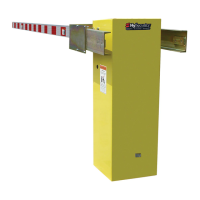
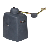
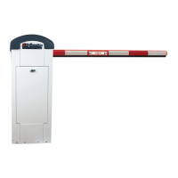
1 = SlideDriver (HSG) all models
except 50VF series
2 = SwingRiser (HRG)
3 = HydraLift (HVG)
4 = StrongArm (HTG)
5 = SlideWinder 24
6 = SlideWinder 38
7 = SlideDriver 50VF
8 = StrongArm CRASH
9 = HydraSwing
10 = HydraSupply XL
Select the appropriate number for the
operator.
NOTE: This menu item only appears if the
Smart Touch Controller is being replaced.
CAUTION: If you are replacing an
STC board, remember to transfer the
operator’s menu settings from the
existing board to the replacement
board. Refer to the installation
instructions that accompany the
replacement STC board.
Not applicable
(N/A)
AD 0
AC/DC GATE
0 = gate disabled
1 = AC (alternating current)
2 = DC battery-power
3 = HyInverterAC – Power Supply
Usually, power type (AC or DC) is factory
set. Select the type of power that the gate
operator uses and is appropriately wired for.
Not applicable
(N/A)
SP 0
SET SPEED
(or indicate Modbus
control)
0 = gate disabled
1 = No ModBus communication**
2 = 2 ft/s
3 = 3 ft/s
**NOTE: A setting of 1 indicates no
ModBus communication or wiring is
present. The VFD uses its factory settings
to control speed.
NOTE: This menu item only appears if the
SlideDriver operator is part of the 50VF
series. It does not appear with any other
operator type.
Set the maximum speed for the gate.
CAUTION: Slow Down extended limit
ramps must be installed on the drive
rails!
See SlideDriver Standard and Slow Down
Limit Ramps on page 31.
N/A
LL 0
LEARN LIMITS
0 = Normal operation
1 = Reset limits
A setting of 1 places operator into its learn
limits mode which allows you to reset gate’s
open and close positions.
UC 0
USAGE CLASS
0 = gate disabled
1 = single family dwelling
2 = multi-family
3 = industrial *
4 = guarded location *
*not serving the general public
Assign operator’s Usage Class designation
per UL 325 standards. See “Identifying Gate
Operator Category and Usage Class” on
page 11. The installer must designate a
usage class before operator will function.
N/A
SH 0
GATE HANDING
0 = gate disabled
R = Right hand
L = Left Hand
Handing determines which way gate opens
as you view it from operator side. If gate
handing is changed after initial setup,
operator resets limits. LEARN OPEN display
appears when you exit Installer Menu.
N/A
BU 0
LOUDEST BUZZER
0 = buzzer not set
1 = Frequency 1 * (on)
2 = Frequency 2 * (on)
*Select the loudest buzzer
Usually, set at the factory. If menu item
appears, select either buzzer 1 or 2. Make
sure to choose the loudest audible buzzer
sound for your operator type.
N/A
FD 0 (OFF)
FACTORY DEFAULTS
0 = user settings (custom)
1 = reload factory settings
Globally restores all menu settings back
to new operator status. Select setting 1 to
return operator to factory defaults.
NOTE: If factory defaults are restored, the
UL usage class, handing, gate weight, and
any other modied menu settings will need
to be reprogrammed.
N/A

 Loading...
