2. Wiring
Fieldbus Communication
47
RCP6
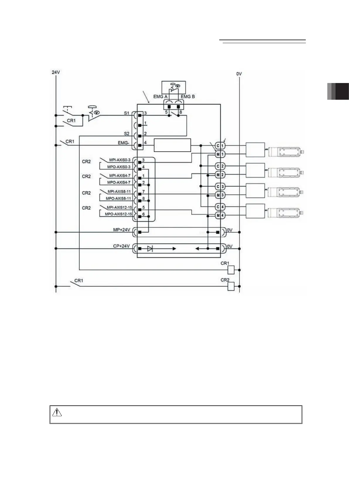
3) Example of stop supplying external motor power at emergency stop input.
Note 1 RCM-P6GW : When there is nothing plugged in the SIO connector, S1 and S2 are
short-circuited inside the controller.
RCM-P6GWG : When there is nothing plugged in the SIO connector, S1 and S2 are not
short-circuited.
To make them short-circuited, have the enclosed dummy plug DP-5
plugged in the SIO connector. [Refer to 2.3.6]
Note 2 When the motor power must be disconnected externally for safety category compliance,
apply a safety rated relay between MPI-AXIS
½
and MPO-AXIS
½
. Choose one that is
capable to open and close with the motor current consumption of the connected actuator
[Refer to 1.2 List of Basic Specifications.]. (
½
: Slot Number)
Note 3 The rating for the emergency stop signal (EMG-) to turn ON/OFF at contact CR1 is 24V DC
and 10mA or less.
Note 4 For CR1, select the one with coil current 0.1A or less.
Caution: When supplying the power by turning ON/OFF the 24V DC, keep the 0V being
connected and have the +24V supplied/disconnected (cut one side only).
Emergency
Stop
Release
Switch
Emergency
Stop Switch
Emergency Stop Switch
on the Teaching Pendant
RCP6S
Gateway Unit
System I/O
Connector
(Note3)
(Note2)
(Note2)
(Note2)
(Note2)
Emergency Stop
Detection Circuit
Drive Cutoff Coeenctor
Axis Power
Supply Connector
(M)
Axis
Control
Connector
(C)
RCP6S Actuators
(MAX. 16 units)
Hub unit 1
Hub unit 4
Hub unit 3
Hub unit 2
Motor Power Supply Connector
Control Power Supply Connector
(Note2)
(Note4)
SIO Connector
(Note1)
Use a hub unit if necessary.
One hub unit can accept four
units of RCP6S actuators at
maximum or a controller for
RCP6S GW to be connected.
In case a hub unit is not to be
connected, connect an actuator
or a controller for RCP6S GW to
the axis control connector.
 Loading...
