Chapter 3 Installation, iring, Conguration
3.2 Wiring
3-5 ME0416-1A
3.2 Wiring
3.2.1 Wiring of LC Unit Power Supply Connector
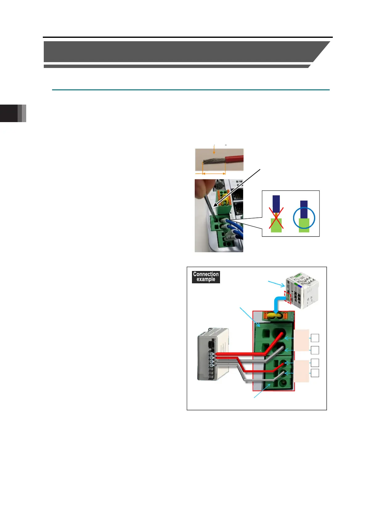
To supply power to the controller, mount the power connector and wire each terminal.
Perform
1 to 4 with reference to the figure and connection diagram below.
[Wiring method to 24V power connector]
(1) Refer to the next page for each wiring
diameter.
(2) The strip length of the wiring is
· MP: 15 mm
· CP: 10 mm
(3) While have a slotted screwdriver
inserted and kept in an inlet besides the
power plug slots and put the power
cables in the terminal inlets.
(4) Remove the screwdriver.
Connect the "24 V" of MP (motor
power connector) to the +24 V terminal
of the 24 VDC power supply.
Connect the "0 V" of MP (motor power
connector) to the 0 V terminal of the
24 VDC power supply.
Connect the "24 V" of CP (control
power connector) to the +24 V terminal
of the 24 VDC power supply.
Connect the "0 V" of CP (control power
connector) to the 0 V terminal of the
24 VDC power supply.
Gateway unit
24VDC power
supply
24 V
0 V
24 V
0 V
Strip length
crewdriver
 Loading...