Chapter 4 PLC Features
4.1 Device Memory
ME0416-1A 4-5
4.1.6 OM_SM [Bit Memory : For System]
Bit memories for system are to be assigned with system data as shown below. There are 128
points available from SM0 to SM127.
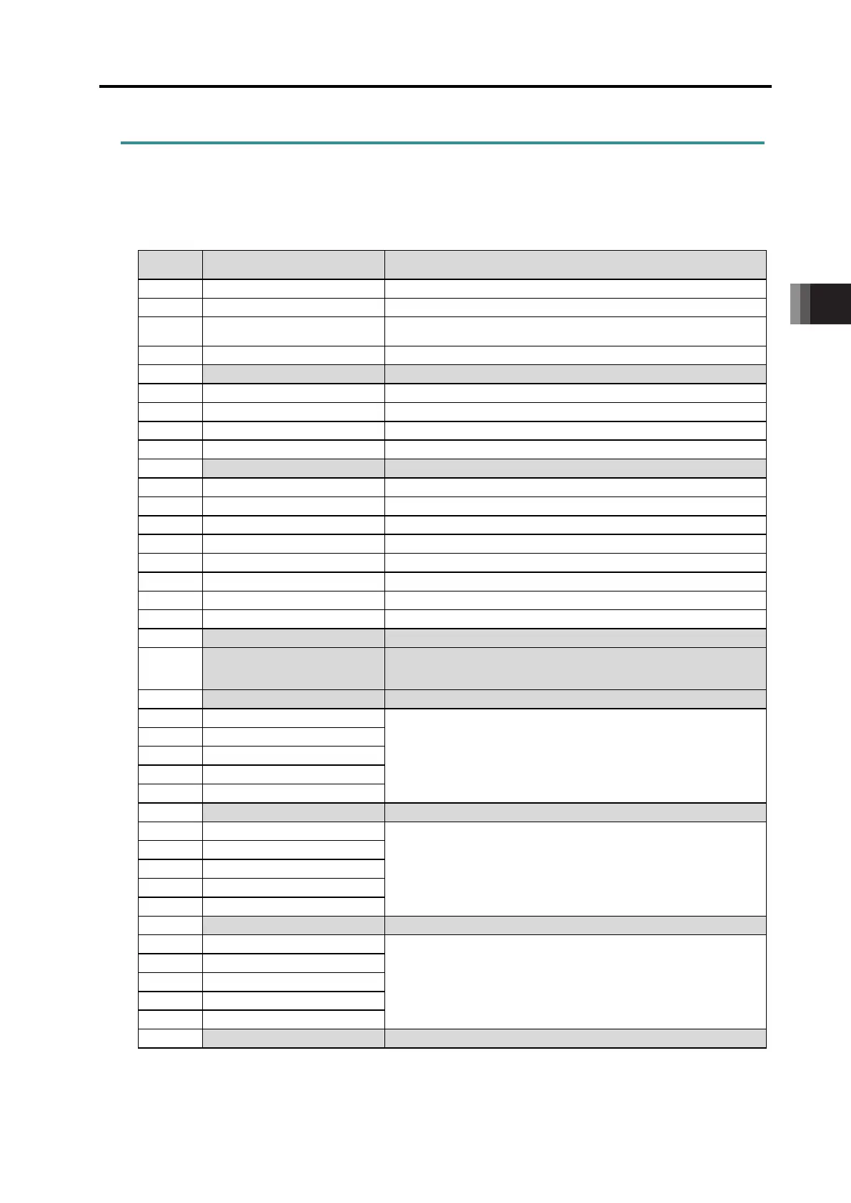
Relation between SM Signals and System Data Assignment (1/2)
Assignment Details Remarks
SM1 1st Scan Flag
SM2 Calculation Error Flag
Turns on when error occurred while ladder executed
An error code should be stored in SD2 and error step in SD3.
Turns on when STC Command used and off when CLC Command used
SM11 0.2-second Clock Reversed every 0.2sec
Gets reversed at the timing indicated in SD13
PIO Unit 0_I/O Power supply Voltage Drop
External I/O power supply voltage drop on 1st PIO unit counted from LC unit side: On
SM17
PIO Unit 1_I/O Power supply Voltage Drop
External I/O power supply voltage drop on 2nd PIO unit counted from LC unit side: On
PIO Unit 2_I/O Power supply Voltage Drop
External I/O power supply voltage drop on 3th PIO unit counted from LC unit side: On
PIO Unit 3_I/O Power supply Voltage Drop
External I/O power supply voltage drop on 4th PIO unit counted from LC unit side: On
PIO Unit 4_I/O Power supply Voltage Drop
External I/O power supply voltage drop on 5th PIO unit counted from LC unit side: On
PIO Unit 5_I/O Power supply Voltage Drop
External I/O power supply voltage drop on 6th PIO unit counted from LC unit side: On
SM22
PIO Unit 6_I/O Power supply Voltage Drop
External I/O power supply voltage drop on 7th PIO unit counted from LC unit side: On
PIO Unit 7_I/O Power supply Voltage Drop
External I/O power supply voltage drop on 8th PIO unit counted from LC unit side: On
SM32 Reserved
Setting is to be established in GW Parameter for RCON-LC while it was in
the output retaining setting at stop (output retained at stop: on, output
compulsorily off at stop: off) for previous models.
SM33-39 Reserved
Power Supply Unit 0_ Link Status
In link: On
Turns on when the communication between RCON-LC and The power
supply unit is established in normal condition and RCON-LC is identified
as valid.
Power Supply Unit 1_ Link Status
Power Supply Unit 2_ Link Status
Power Supply Unit 3_ Link Status
SM44 Power Supply Unit 4_ Link Status
Power Supply Unit 0_Fan Warning
In Fan Warning: On
The fan warning should occur when fan revolution is dropped by 30%.
Power Supply Unit 1_Fan Warning
Power Supply Unit 2_Fan Warning
SM51
Power Supply Unit 3_Fan Warning
Power Supply Unit 4_Fan Warning
Power Supply Unit 0_Fan Error
In Fan Error: On
The fan error should occur when fan revolution is dropped by 50%.
Power Supply Unit 1_Fan Error
SM58 Power Supply Unit 2_Fan Error
Power Supply Unit 3_Fan Error
Power Supply Unit 4_Fan Error
 Loading...