Chapter 4 PLC Features
4.1 Device Memory
ME0416-1A 4-3
4.1.1 OM_X [Bit Memory : For Input Assignment]
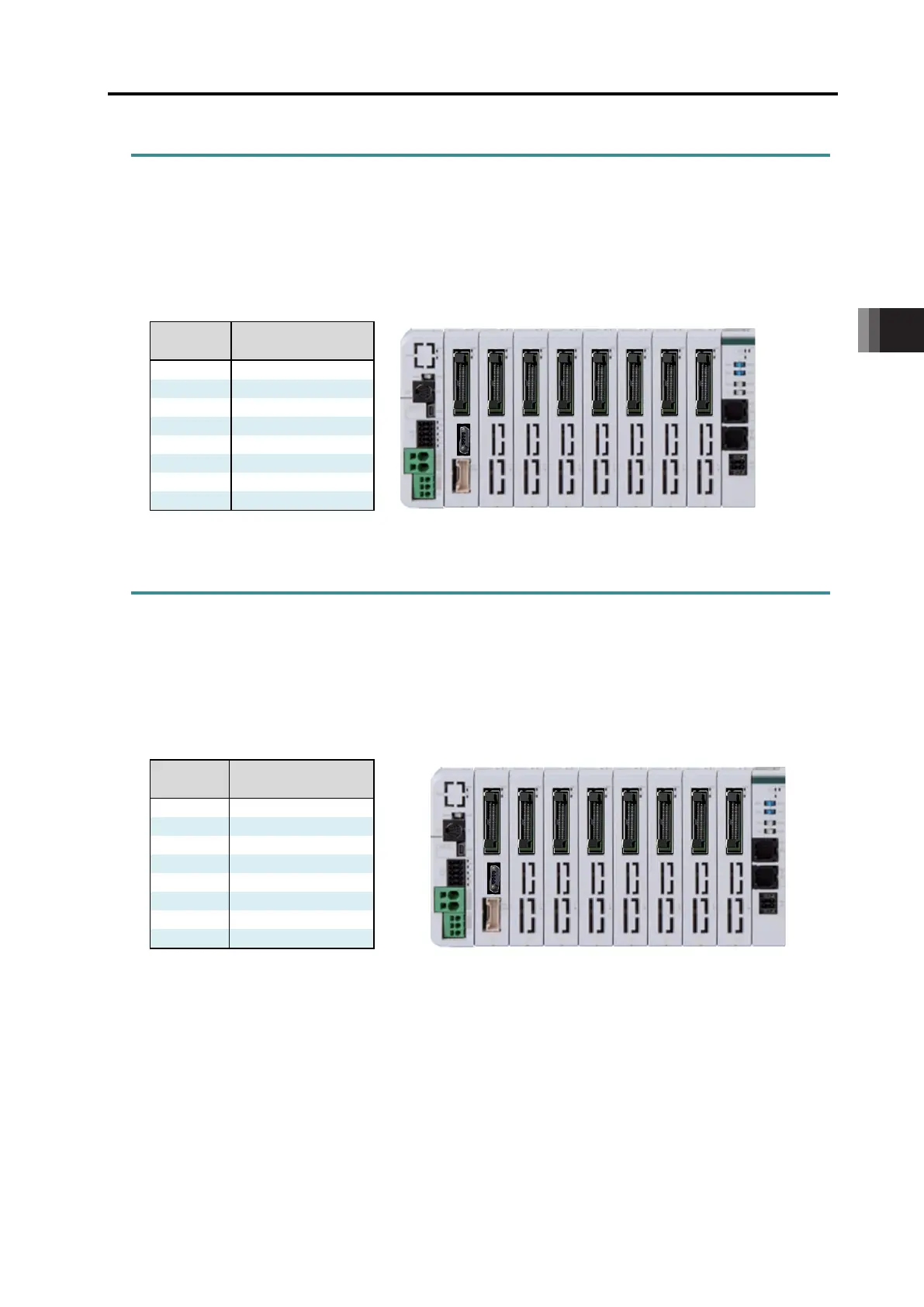
OM_X is to be assigned with the extension PIO inputs. The order of assignments should be from
the nearest to LS Unit. Assign from the nearest with no blank. The relation between X and PIO
connector when assignment was made from the nearest to LC Unit to the PIO connector (input
16 points/ output 16 points) should be as shown below.
Relation between PIO Connector Position and X Assignment
Position
X Assignment
(Hexadecimal)
4.1.2 OM_Y [Bit Memory : For Output Assignment]
OM_Y is to be assigned with the extension PIO outputs. Alike OM-X, the order of assignments
should be from the nearest to LS Unit. Assign from the nearest with no blank. The relation between
Y and PIO connector when assignment was made from the nearest to LC Unit to the PIO
connector (input 16 points/ output 16 points) should be as shown below.
Relation between PIO Connector Position and Y Assignment
Position
X Assignment
(Hexadecimal)
 Loading...