20
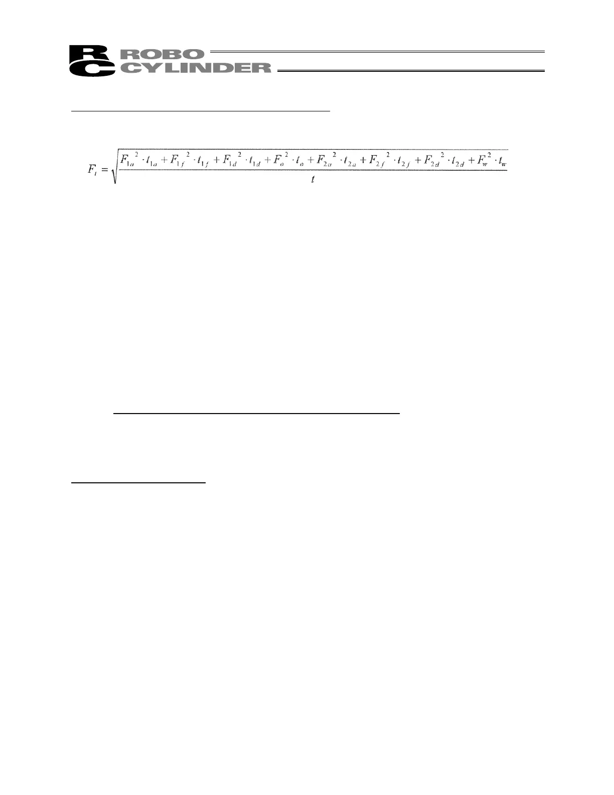
Condition [2] Calculate the thrust for continuous operation.
Assign the above operation pattern to the aforementioned formula to calculate thrust for continuous
operation.
Here,
F
1a
, F
2d
= (M + m) x 9.8 - (M + m) x d = 1058 N
F
1f
, F
2f
= (M + m) x 9.8 = 1068N
F
1d
, F
2a
= (M + m) x 9.8 + (M + m) x d = 1079 N
F
0
= Push command value 200% (2000 kgf) = 19600 N
F
w
= (M + m) x 9.8 = 1068N
t
1a
= t
2a
= t
1d
= t
2d
= Speed 62 mm/s ÷ Acceleration/deceleration 98 mm/s
2
= 0.632 s
t
1f
= t
2f
= (Travel distance 50 mm – (Travel distance during acceleration 19.60 mm + Travel distance during
deceleration 19.60 mm)) ÷ Speed 62 mm/s = 0.174 s
Travel distance during acceleration (deceleration) = Acceleration (deceleration) rate 98 mm/s
2
x
(Acceleration (deceleration) time (t
1a
,
2a
,
1d
,
2d
) 0.632 s)
2
÷ 2 = 19.60 mm
t
o
= 3s, t
w
= 2 s, t = 7.88 s
From the above, the following result is obtained:
F
w
= 12113 N
Since this is greater than the rated thrust of 10200 N specified for the ultra high-thrust actuator with 1.25
(2t) lead, the actuator cannot be operated based on this operation pattern.
Now, the standby time is increased (duty is lowered) as a countermeasure.
In this example, calculations are repeated by assuming t
1
= 6.12 s (t = 12 s). This time, the following result
is obtained:
F
w
= 9814 N
The actuator can be operated.
 Loading...


