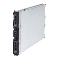
5. Remove the filler module from the selected bay. Store the filler module for
future use.
6. If you have not already done so, touch the static-protective package that
contains the switch module to an unpainted metal part of the BladeCenter unit
for at least two seconds.
7. Remove the switch module from its static-protective package.
8. Ensure that the release latch on the switch module is in the open position
(perpendicular to the module).
9. Slide the switch module into the appropriate switch-module bay until it stops.
10. Push the release latch on the front of the switch module to the closed position.
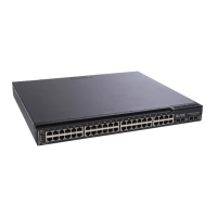
11. Make sure that the LEDs on the switch module indicate that it is operating
properly. Verify that:
v The dc power LED and the ac power LED on each power module are lit.
v The OK LED on each management module is lit.
v The OK LED on each switch module is lit.
12. If you have other switch modules to install, do so now; otherwise, go to step
13.
13. Attach any cables required by the switch module. For the location of the
connectors on the BladeCenter unit, see Eserver BladeCenter Type 8677
Installation and User’s Guide on the IBM BladeCenter Documentation CD.
14. Replace the acoustic attenuation module, if you removed it in step 2 on
page 10.
Chapter 2. Installing and removing a switch module 11

 Loading...