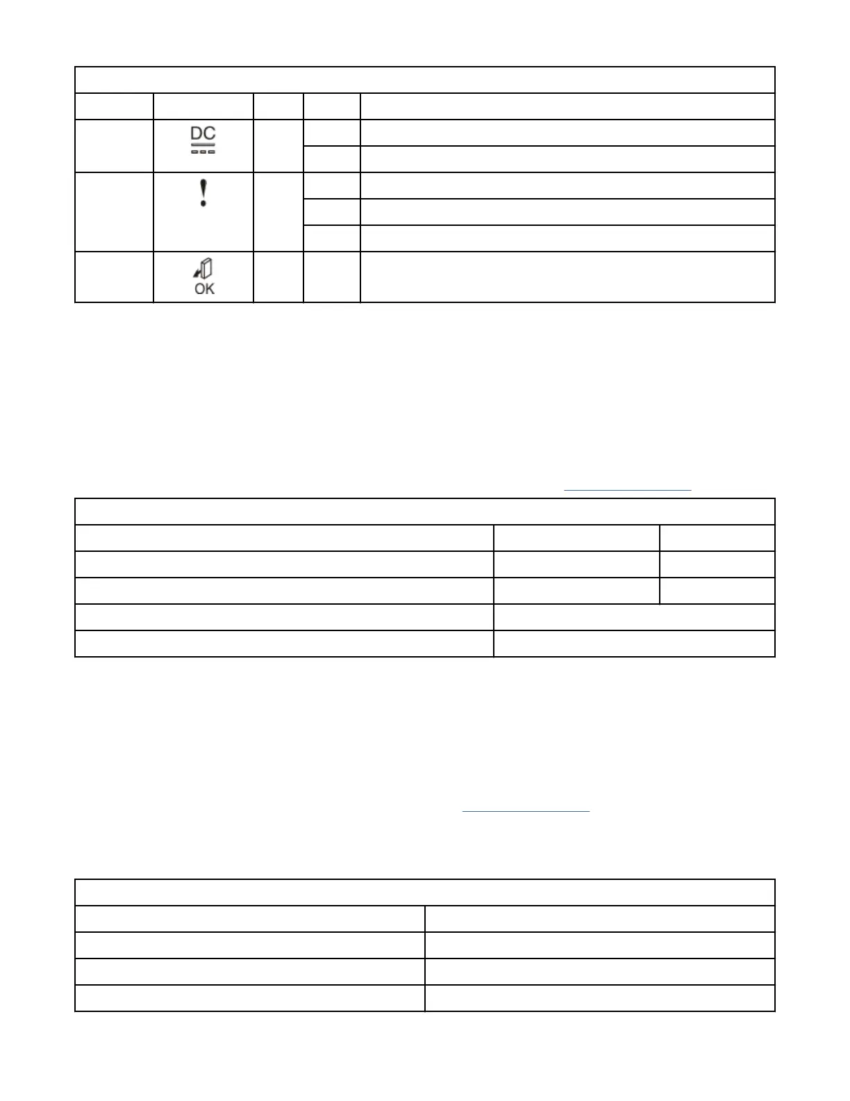
Table 19. DC power supply LED indicators (continued)
Name Label Color State Description
Output
status
Green OFF PSU is not providing DC output power.
ON PSU is providing DC output power.
Fault Ambe
r
OFF No fault detected.
ON PSU fault was detected.
BLINK PSU is being identied. A fault might have been detected.
(None) Blue N/A Not used.
Connecting a DC power supply to a DC power source
An enclosure that is DC powered contains two DC power supply units (PSUs). Each unit must be
connected to a suitable -48V DC power source. To provide redundancy in a power circuit failure, connect
the two PSUs to different DC power sources.
Note: The connection to the DC power source must be made by trained service personnel. Ensure that the
connection is made in accordance with all the requirements of the equipment that is being used.
Use the supplied cables to connect the DC PSUs to the power sources. Use only the IBM supplied DC
power cable (IBM part number 00AR087) to connect the unit to a DC power source.
The supplied power must meet the input requirements that are listed in Table 20 on page 19.
Table 20. DC power supply input requirements
Requirement Min Max
Voltage (V DC) -48 -60
Instantaneous (V DC for < 1 second) -36 -75
Inrush current at initial turn on (-48V DC) 34 A
Out of spec time before power off is signaled 5 ms
Important: Each PSU cable must be protected by a 20A circuit breaker. These instructions assume that
the circuit breaker is separate from the DC power distribution unit. Refer to the DC power distribution unit
documentation and the circuit breaker documentation for details. Follow the instructions that are given
there for connecting the circuit breaker to the power distribution unit and for connecting the DC power
cable to the circuit breaker.
One end of the cable ends in a plug that ts the DC PSU. At the other end of the cable, each individual wire
ends with a 6 mm diameter ring terminal that is designed to t an M6 stud. Provide adequate strain relief
after you attach the ring terminals to the power source. Table 21 on page 19 lists the wire colors.
If it is necessary to replace the ring terminals with a different connector, choose a suitably sized and rated
UL-listed connector that is appropriate for the wire gauge and available current. Install the ring terminals
according to the instructions provided by the manufacturer.
Table 21. DC cable wire color coding
Color Function
Blue Return
Green / Yellow Ground
Brown -48V
Chapter 3. Before you begin the installation 19