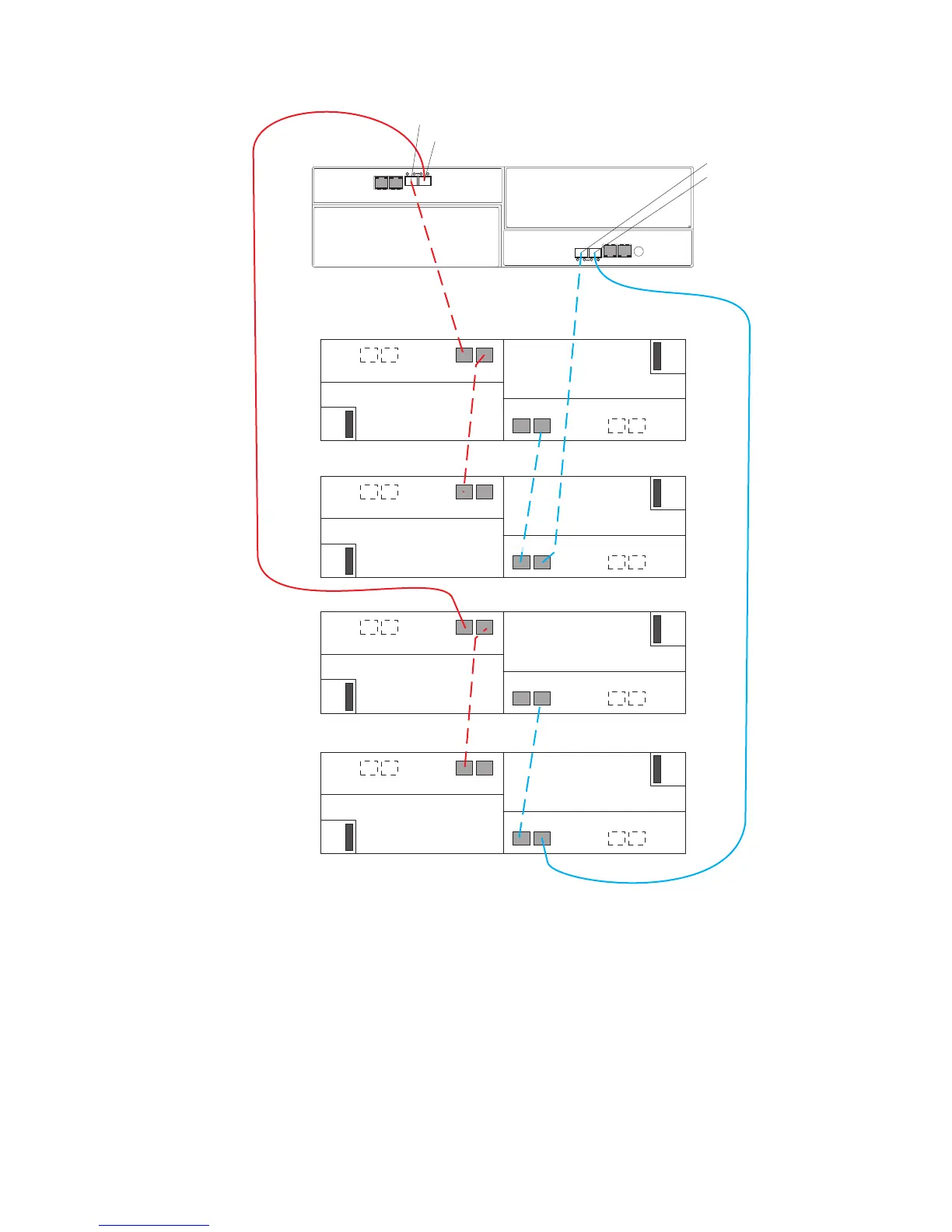
Perform the following steps to create the cabling scheme shown in Figure 49:
1. Connect port 1A on the left ESM in EXP520 one to port 1B on the left ESM in
EXP520 two.
2. Connect port 1A on the right ESM in EXP520 two to port 1B on the right ESM in
EXP520 one.
3. Connect port 1B on the left ESM in EXP520 one to port 2 of drive channel 1 on
the DS5020.
4. Connect port 1B on the right ESM in EXP520 two to port 1 of drive channel 2
on the DS5020.
1A
1B
DS5020
Port 2, drive channel 1
1A
1B
1A
1B
1A
1B
Port 1, drive channel 1
Port 1, drive channel 2
Port 2, drive channel 2
1A
1B
1A
1B
1A
1B
1A
1B
EXP520 one
EXP520 two
EXP520 three
EXP520 four
Figure 49. One DS5020 and four EXP520 storage expansion enclosures behind a pair of
DS5020 drive ports
76 IBM System Storage DS5020 Storage Subsystem: Installation, User’s, and Maintenance Guide

 Loading...


