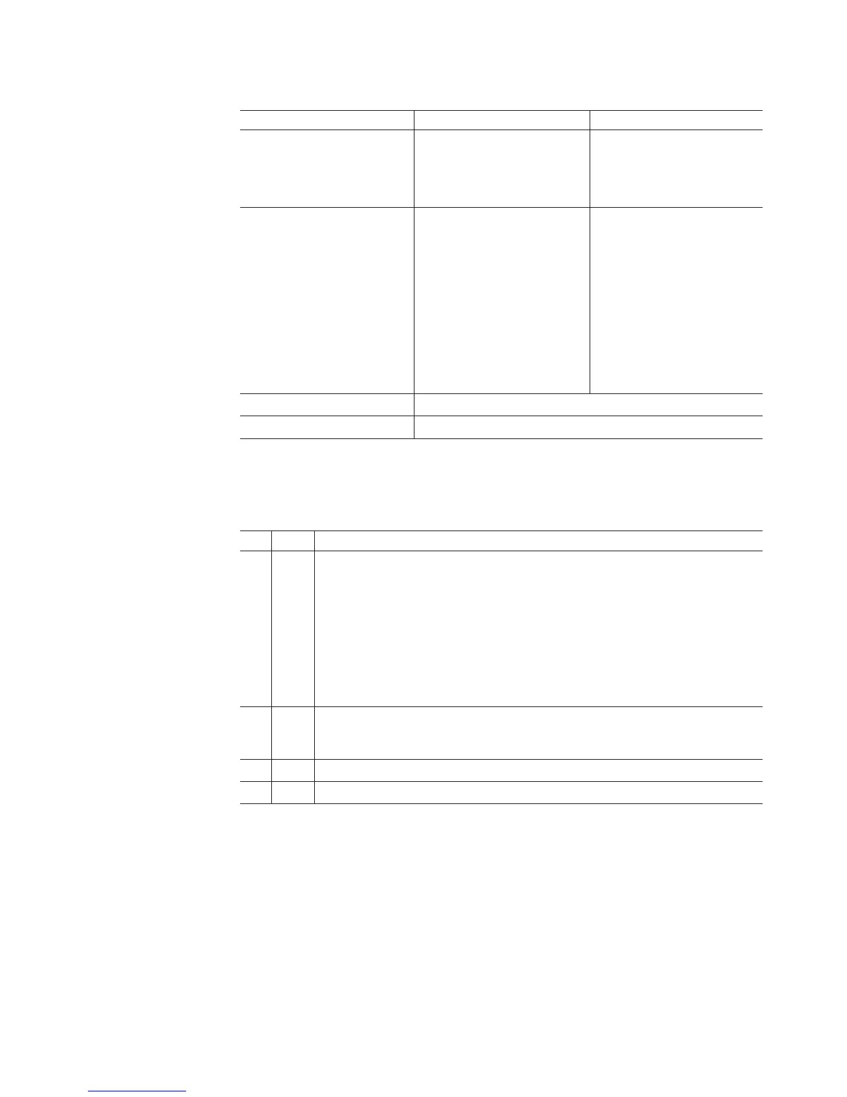
Table 17. Rear controller LEDs, controls, and connectors (continued)
LED Normal Status Problem Status
Ethernet Link Activity On - link established
Off - no link established
Flashing - activity
Not applicable
Drive Channel Port Bypass
(One LED per port)
Note: The drive channel
consists of two FC ports. This
LED indicates the drive port
bypass status of one of the
two FC ports that comprise a
drive channel. The other drive
channel port has its own
Drive Channel Port Bypass
LED.
Off
(Also off if no SFP
connected)
On - No valid device detected
and port is bypassed
Drive Channel Speed - L1 See Table 18.
Drive Channel Speed - L2 See Table 18.
The L1 and L2 LEDs for each Fibre Channel host and drive channel combine to
indicate the status and the operating speed of each host and drive channel.
Table 18. Host and drive channel LED definitions
L1 L2 Definition
Off Off When both LEDs for a host or drive channel are off, this indicates one or more
of the following conditions:
v The host or drive channel ports are bad or the SFPs are faulty.
v An SFP module is inserted with no Fibre Channel cable attached.
Note: If the SFP is inserted in a drive port with no Fibre Channel attached,
the associated drive port bypassed LED will also be lit. In addition, the L1
and L2 LEDs will be unlit.
v No SFP module is inserted in one or both of the host or drive ports in the
channel.
On Off The host is operating at 2 Gbps. The drive channel is operating at 1 Gbps.
Note: This pattern is not applicable in the drive port because the DS5020 does
not support 1 Gbps Fibre Channel speed.
Off On The host is operating at 4 Gbps. The drive channel is operating at 2 Gbps.
On On The host is operating at 8 Gbps. The drive channel is operating at 4 Gbps.
Seven-segment numeric display LEDs
The numeric display consists of two seven-segment LEDs that provide information
about enclosure identification and diagnostics. Figure 72 on page 110 shows the
numeric display and the diagnostic LED.
Chapter 4. Operating the storage subsystem 109