Attention:
Before you turn on the power to the DS5020 storage subsystem, it must be
populated with at least two E-DDMs.
If at least two E-DDMs are not installed in the DS5020, an insufficient load to the
enclosure power supplies might cause them to intermittently appear as failed,
falsely indicating the power supplies are bad. All of the E-DDMs in the DS5020
storage subsystem and the connected storage expansion enclosure or
enclosures must contain no prior configuration data.
v E-DDM CRU labels: A label is provided on the front of each E-DDM. Use this
label to record the location information for each E-DDM before you remove it.
Make sure that you keep track of the E-DDMs and their corresponding bays.
Also, record the location information in Table 26 on page 174. If you install an
E-DDM in the wrong bay, you might lose data.
v E-DDM LEDs: Each E-DDM CRU tray has two associated LEDs, a green Activity
LED and an amber Fault LED. These LEDs indicate the status for that drive. See
Table 20 for the E-DDM LED states and descriptions.
v E-DDM CRUs are not interchangeable between the DS5020 and other DS4000
storage subsystems.
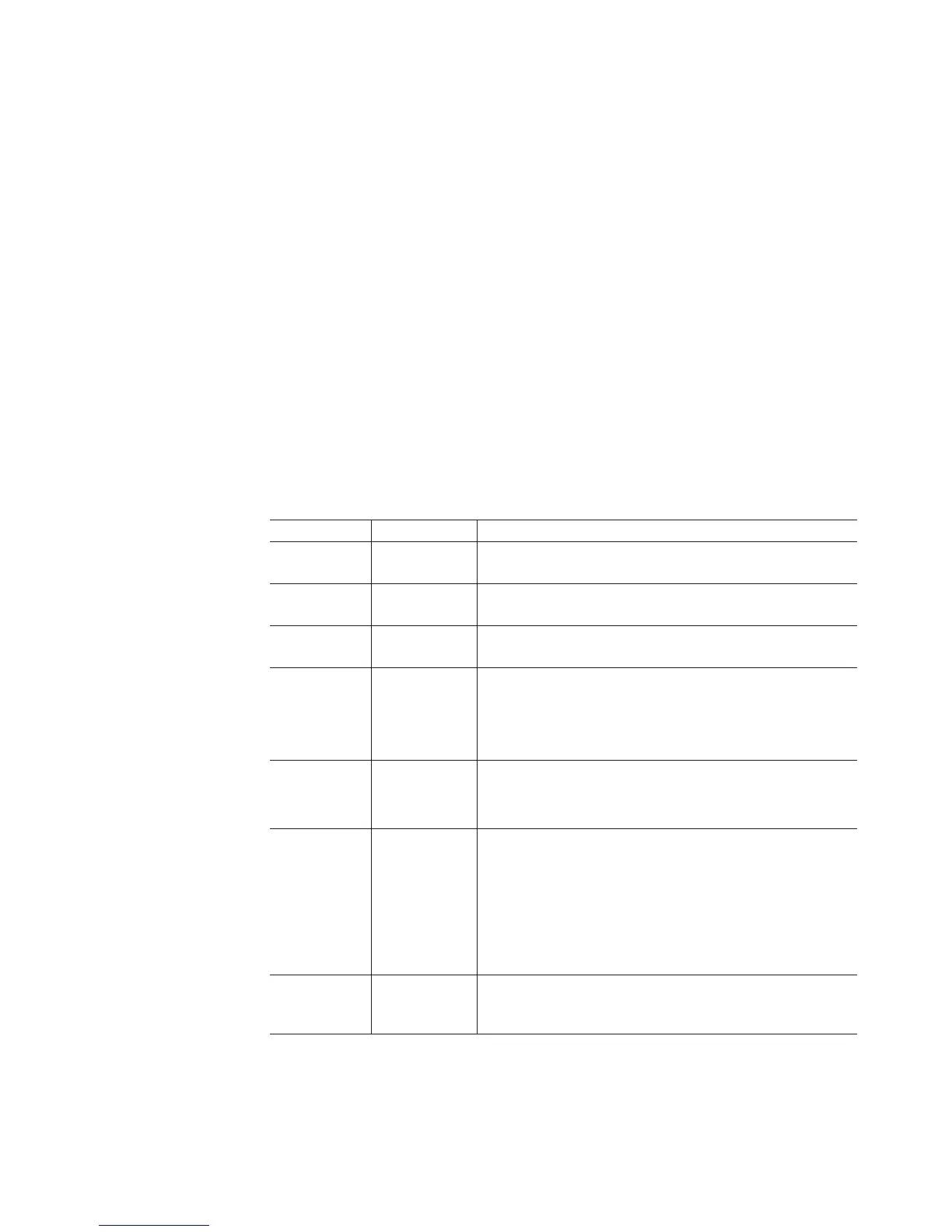
Table 20. Drive LED activity
LED LED state Descriptions
Activity LED Flashing green The green LED flashes to indicate Fibre Channel activity to
the drive.
Activity LED Steady green The green LED lights to indicate that the drive is properly
installed and is spun up by the DS5020 controller.
Fault LED Flashing
amber
The amber LED flashes to indicate that a drive has been
identified by the software.
Fault LED Steady amber The amber LED lights to indicate a drive failure due to bad
or uncertified drive, or the controller firmware is not at the
minimum version required to support the drive. The green
activity LED might flash once every 2 seconds, remain
steady green, or be unlit.
Activity and
Fault LEDs
All unlit Check for and resolve one of the following situations:
v DS5020 is turned off.
v DS5020 link rate speed is not set correctly.
Activity LED Flashing once
every 2
seconds
Check for and resolve one of the following situations:
v The controller did not complete the boot process.
v Storage subsystem controller firmware is not correct.
Note: Drives are also spun down because they are in a
"not compatible state" or "exported state", or because the
controller firmware is not at the minimum version required
to support the drive.
Activity and
Fault LEDs
Flashing
together in a
certain pattern
Drive failure due to the incorrect link rate speed setting or
internal drive hardware failures.
v Fibre Channel loop IDs: When you install an E-DDM in the storage subsystem,
the drive tray connects into a printed circuit board called the midplane. The
midplane sets the Fibre Channel loop ID automatically, based on the setting of
the enclosure ID switch and the physical location (bay) of the drive CRU.
Chapter 5. Replacing components 131