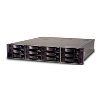
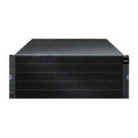
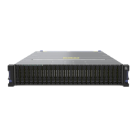
disconnecting the storage subsystem logical drives from the host before
the storage subsystem is powered off.
b. Turn off power to the storage subsystem before you turn off power to the
storage expansion enclosures. Turn off both power supply switches on the
back of the storage subsystem.
CAUTION:
This unit has more than one power source. To remove all power from
the unit, all MAINS must be disconnected.
CAUTION:
The power switch on the power supply and fan unit does not turn off
the electrical current supplied to the device. The DS5020 storage
subsystem might also have more than one connection to power. To
remove all electrical current from the device, ensure that all power
cords are disconnected from the power supply and fan unit input
connectors.
c. Turn off power to other supporting devices (for example, management
stations, Fibre Channel switches, or Ethernet switches).
7. Use the procedures in “Replacing hot-swap E-DDMs” on page 133 to remove
the E-DDMs that you want to replace. Use the procedures in “Installing
hot-swap E-DDMs” on page 132 to install the new E-DDMs into the storage
subsystem.
8. After you install all the new E-DDMs, check the system documentation for the
hardware devices that you intend to power on, and then determine the proper
startup sequence. Use the following power-on sequence, where applicable:
a. Turn on the power to the supporting devices (for example, Ethernet
switches and management stations) before you turn off power to the
storage subsystem.
b. You must turn on the storage expansion enclosures before the storage
subsystem. The controllers might not recognize the correct configuration if
the E-DDMs are powered up after the storage subsystem. For instructions
on powering up the storage subsystem, see the storage subsystem
documentation.
c. Turn on the power to the storage subsystem; then restart or turn on the
power to the host.
9. Turn on the power to each device, based on the power-on sequence in step 8.
To turn on power to the storage subsystem and the storage expansion
enclosures, turn on the power supply and fan unit switches on the back of the
storage subsystem. You must turn on both power supply and fan unit switches
to take advantage of the redundant power supplies.
10. Check the green Drive activity LEDs and the amber Drive fault LEDs above
the new E-DDM CRUs.
Make sure that the Drive activity LEDs are on and the Drive fault LEDs are off.
Note: The Drive fault LEDs might flash intermittently while the E-DDMs spin
up.
Chapter 5. Replacing components 137

 Loading...


