Rev 2015-03-02 35
GV10x OPERATION AND SAFETY MANUAL
Appendix F: Tables and Figures
Table 4-1. Range of Allowed Parameter Settings ......................................................................... 14
Table 4-2. Variable Constriction Turns vs. Pressure .................................................................... 24
Table C-1. API for GV10x Controllers Manufactured Prior to Jan 15, 2015 31
Table C-2. New API Commands for GV10x Controllers Manufactured After Jan 15, 2015 32
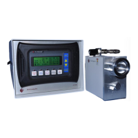
Figure 1-1. BT Model ..................................................................................................................... 9
Figure 1-2. 2U Model ..................................................................................................................... 9
Figure 1-3. Sources P3, P4, and P5 ............................................................................................... 10
Figure 3-1. Source and BT (benchtop) Controller Back Panels ................................................... 13
Figure 3-2. Source, Spooler and Pirani Gauge Assembly. ........................................................... 13
Figure 4-1. PLC Self-Test Screen 1 .............................................................................................. 14
Figure 4-2. PLC Self-Test Screen 2 .............................................................................................. 14
Figure 4-3a. Information Screen, lines 1-4 ................................................................................... 15
Figure 4-3b. Information Screen, lines 5-8 ................................................................................... 15
Figure 4-3c. Information Screen, lines 7-10 ................................................................................. 15
Figure 4-4. Operating Parameters Screen ..................................................................................... 16
Figure 4-5a. GV10x Remote Control Software ............................................................................ 17
Figure 4-5b. GV10x-RC15 Control tab ........................................................................................ 17
Figure 4-5c. GV10x-RC15 Setup tab............................................................................................ 17
Figure 4-6. C2 Tuning Knob ........................................................................................................ 22
Figure 4-7. Operating Parameters Screen with Tuning Voltage highlighted ............................... 22
Figure 4-8. Terminals at Rear of Source ...................................................................................... 22
Figure 4-9. 1/8” S/S Metal Compression Fitting, Gas Inlet Filter, Variable Constriction &
Isolation Valve .............................................................................................................................. 24
Figure 5-1. Lockout Clamshell ..................................................................................................... 25
Figure B-1. Source Interlock......................................................................................................... 29
 Loading...