Rev 2015-03-02 22
GV10x OPERATION AND SAFETY MANUAL
4.3. How to Tune the GV10x Source
The GV10x Downstream Asher includes a matching network, which can be adjusted, or
tuned, to minimize the reflected power (Wr) and maximize the power delivered to the
plasma. This network is factory tuned, but it may require adjustments if ignition does not
occur, if the reflected power is too high (>20% of the Actual Power), or if the Actual
Power reading is not within 15% of the Set Power. To tune, follow steps 4.3.1 through
4.3.5.
Two components, C1 and C2, are used for tuning the Source to the Controller. C1 is
preset by ibss Group prior to shipping. Users should not adjust C1. C2 is adjusted by a
knob on the Source and is the ONLY component to be used by non-ibss Group
personnel. The knob used to adjust C2 is found on the front of the P3 and P4 Source (see
Figure 4-6) and on the rear of the P5 Source. Refer to step 4.3.4 for details.
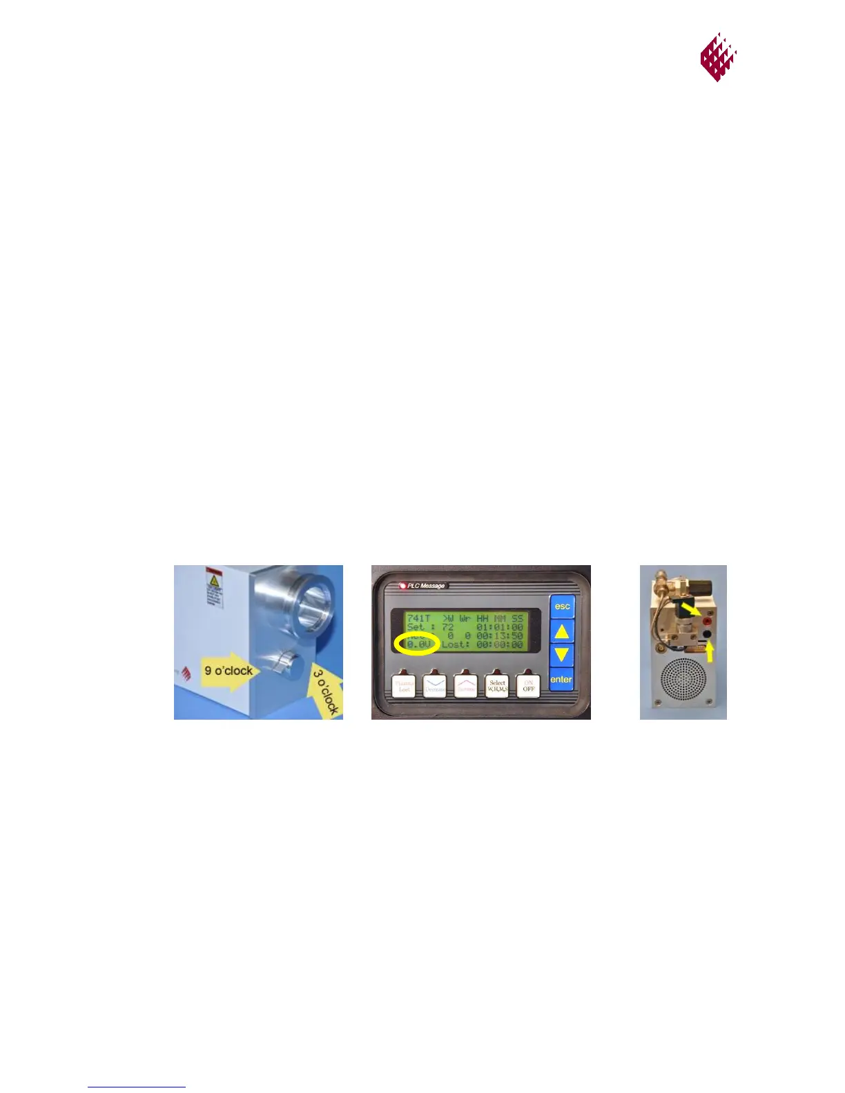
4.3.1. Monitor the tuning voltage
The Tuning Voltage, VDC, is a measure of how well the matching network is adjusted
and is displayed in the bottom row of text on the BT Controller Operating Parameters
screen, Figure 4-7. Tuning Voltage can also be monitored at the Source rear panel (P3
and P4 only) and in the GV10x Remote Control Software. For the 2U Controller or if the
BT Controller is out of reach of the Source, connect red & black voltmeter leads to red &
black voltmeter terminals (yellow arrows in Figure 4-8) on the Source rear panel (P3, P4
only )and set meter to 5 VDC.
4.3.2. Set RF power level to 30 watts and time to 1 hour.
4.3.3. Press ON to open isolation valve and apply RF to the Source.
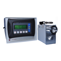
4.3.4. If plasma will not ignite, rotate C2 knob slowly to maximum Tuning Voltage.
When reading ≥5VDC, the plasma will ignite. Note: C2 knob can only be rotated
through 180 degrees from the 3 o’clock position to the 9 o’clock position. The best tuning
most often occurs when the C2 pointer mark is between roughly 7 o’clock position and 8
o’clock position.
Figure 4-8.
Terminals at
Rear of Source
Figure 4-6.
C2 Tuning Knob
Figure 4-7.
Operating Parameters Screen
with Tuning Voltage highlighted
 Loading...