66
9
INSTALLATION AND CONNECTIONS
New2001
9
INSTALLATION AND CONNECTIONS
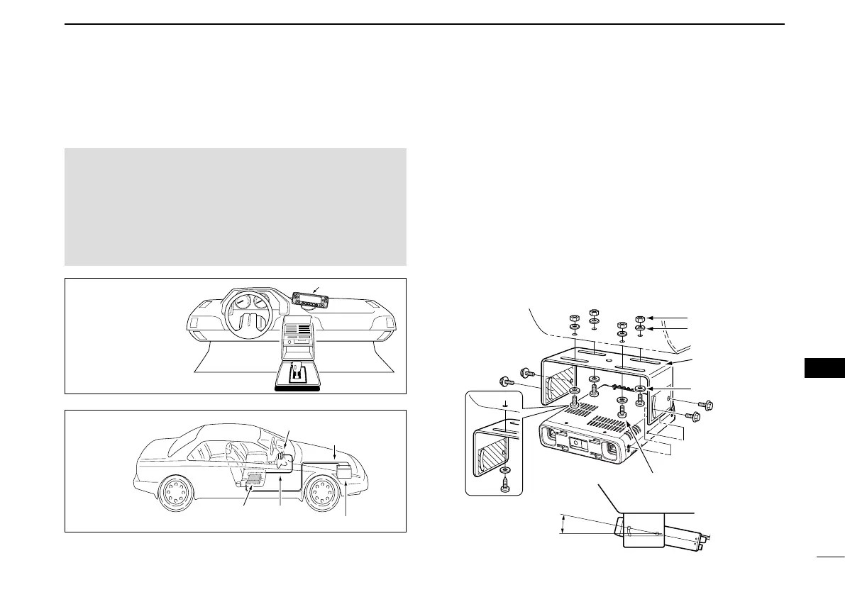
■ Installing in a vehicle
(Except for the EU countries’ transceiver)
CAUTION: NEVER place the main unit or remote controller
where normal operation of the vehicle may be hindered or
where it could cause bodily injury.
CAUTION: NEVER place the main unit or remote controller
where air bag deployment may be obstructed.
DO NOT place the transceiver or remote controller where
hot or cold air blows directly onto it.
•Remote controller
installation
Controller
DC power cable
Battery (12 V)
Controller
cable
Main
unit
•Main unit
installation
D Using the mounting bracket
You can install the main unit on the dashboard or the console
of your vehicle with the optional MBF-4
m o b i l e b r a c k e t .
Drill 4 holes where the mounting bracket is to be installed. q
•Approximately5.5~5.6mm(0.21~0.22inch)(d)whenusingnuts;
approximately 2~3 mm (0.08~0.12 inch)(d) when using self-tap-
ping screws.
Insert the supplied screws, nuts and washers through the w
mounting bracket and tighten.
Adjust the angle to suit your needs. e
25˚
Nut
Spring washer
When using
self-tapping
screws
Flat washer
Mounting
nut
Mounting
bracket
Screw
 Loading...