4
1
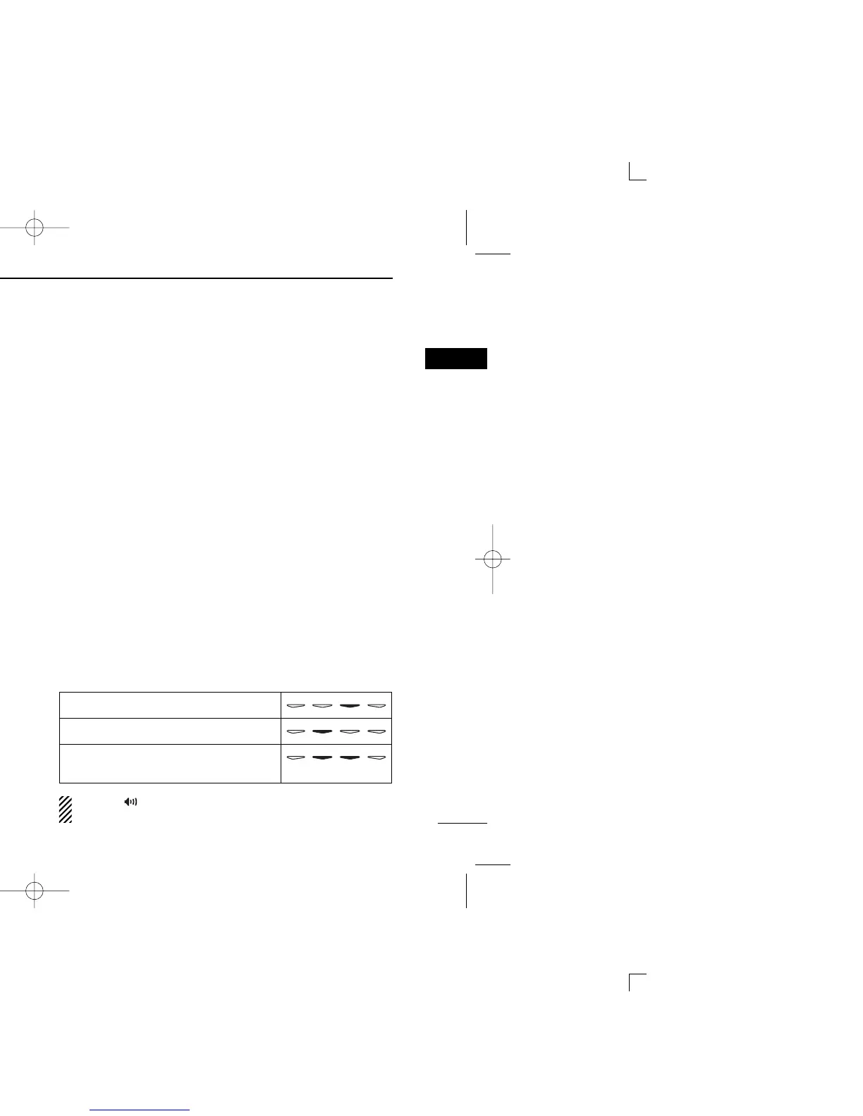
PANEL DESCRIPTION
1
■ Function display
q TRANSMIT INDICATOR
Appears while transmitting.
w BUSY INDICATOR
Appears while receiving a signal or when the squelch is
open.
e SIGNAL STRENGTH METER
Indicates relative receive signal strength level.
r LOW POWER INDICATOR
Appears when low output power is selected.
[High/Low] must be assigned to the desired program-
mable key using the optional CS-400PRO
CLONING
SOFTWARE
when change the output power.
t SQUELCH INDICATOR
Appears when the channel is in ‘Audible’ condition
(SelCall/CTCSS mute is released).
y DUPLEX INDICATOR
Appears when the duplex operation is selected.
u SCRAMBLER INDICATOR
Appears when the scrambler function is activated. (Optional
UT-109 (#02)/UT-110 (#02) SCRAMBLER UNIT is required.)
i SELCALL/5TONE INDICATOR
Appears when the specified Selcall/5-tone is received.
o SCAN CHANNEL INDICATOR
Appears when the selected memory channel is specified
as a scan channel.
!0 ALPHANUMERIC DISPLAY
Displays the operating channel number, channel names,
Set mode contents, DTMF numbers, etc.
!1 UNDER BAR INDICATOR
➥ Shows the channel mute condition (‘Inaudible’ condi-
tion) as below.
➥ The left under bar blinks in Function mode, and lights in
Set mode.
➥ Appears in Set mode when the key under the indicator
can be activated.
During “” appears, the channel is
‘
Audible’ condition
even if the channel is in mute condition.

 Loading...