EasyManua.ls Logo

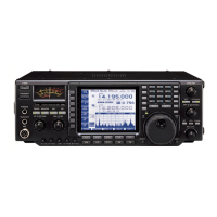
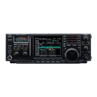
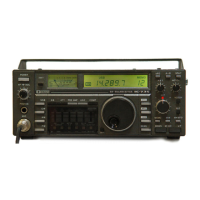
Icom IC-756 User Manual

Icom IC-756
72 pages
To Next Page IconTo Next Page
Page #1 background imageLoading...
Page #1 background image
INSTRUCTION MANUAL
i756
HF/50 MHz
ALL MODE TRANSCEIVER

Table of Contents

Other manuals for Icom IC-756

Questions and Answers:

Icom IC-756 Specifications

General IconGeneral
Antenna Impedance50 ohms
Power Supply Requirement13.8 V DC ±15%
Frequency Range0.03-60 MHz
ModesSSB, CW, RTTY, AM, FM
RF Output Power100W (SSB/CW/FM), 40W (AM)
Receiver TypeSuperheterodyne
Intermediate Frequencies64.455 MHz/455 kHz
SensitivitySSB/CW: 0.16 μV
SelectivitySSB: 2.4 kHz/-6 dB
Current Consumption2.0 A (Receive), 20 A (Transmit)

Summary

Important Precautions and Definitions

Important Safety Instructions

Emphasizes careful reading of the manual and saving it for future reference.

General Precautions

Covers high voltage warnings, electrical hazards, environmental, operational, and equipment usage guidelines.

Explicit Definitions

Defines the scope of WARNING, CAUTION, and NOTE terms used in the manual.

Panel Description Overview

Front Panel Controls

Describes the function of buttons, switches, dials, and connectors on the front panel.

Microphone (HM-36) Details

Details the functions and connector pin assignments of the HM-36 microphone.

LCD Display Indicators

Explains the indicators and readouts shown on the transceiver's LCD screen.

Screen Menu Arrangement

Illustrates how to navigate between different screens like Spectrum Scope, Filter, Memory, and Set Mode.

Rear Panel Connectors

Details the function of various connectors on the rear panel of the transceiver.

Installation and Connections Guide

Unpacking and Initial Setup

Covers unpacking procedures, selecting a location, grounding, and antenna connection.

Required Connections

Details essential connections for front and rear panels, including CW key, microphones, antennas, and power.

Advanced Connections

Explains advanced front and rear panel connections for external equipment like computers, tuners, and speakers.

Power Supply Connections

Illustrates how to connect Icom and non-Icom DC power supplies, and vehicle batteries.

Linear Amplifier Connections

Provides diagrams and instructions for connecting IC-4KL, IC-2KL, and non-Icom linear amplifiers.

External Antenna Selector or Antenna Tuner Connections

Details connections for external antenna selectors (EX-627) and tuners (AH-3, IC-AT500).

FSK and AFSK (SSTV) Connections

Explains connections for FSK/RTTY and AFSK/SSTV using ACC sockets or the microphone connector.

CI-V Remote Control Jack Information

Describes CI-V connection examples, data formats, and command tables for computer control.

Frequency Setting Procedures

Initial Power-On and Settings

Guides through CPU resetting, initial settings, and checking indicators after power-on.

VFO Description and Operation

Explains the Variable Frequency Oscillator (VFO) function and its differences from memory mode.

Frequency Tuning and Entry Methods

Details setting frequencies using the tuning dial, band keys, and direct keypad entry.

Advanced Tuning Functions

Covers quick tuning steps, 1 Hz step tuning, 1/4 tuning, and auto tuning functions.

Receive and Transmit Operations

Mode Selection and Passband Tuning

Explains available operating modes (SSB, CW, RTTY, AM, FM) and Twin PBT operation.

Noise and Interference Reduction

Details auto notch, noise reduction, and noise blanker functions for improving reception.

Signal Processing Features

Covers APF function, CW/RTTY reverse modes, and CW pitch control for signal clarity.

Filter Selection

Explains how to select 9 MHz and 455 kHz IF filters to adjust the passband width.

Frequency Shift Functions (RIT/ATX)

Details the RIT and ATX functions for shifting receive/transmit frequencies and the calculate function.

Dualwatch Operation

Monitors two frequencies simultaneously for improved reception during dualwatch.

Scanning Operations

Details how to initiate programmed and AF scans during dualwatch.

Split Frequency Operation

Enables transmitting and receiving on different frequencies, with convenient input methods.

Quick Split Function

Facilitates split frequency operation by equalizing frequencies and enabling quick transmit frequency input.

Monitor and VOX Functions

Explains how to monitor transmit signals and use the Voice-Operated Transmission (VOX) function.

Metering, Speech Compression, and SWR

Details the meter functions, speech compressor for improved audio, and SWR reading.

Electronic CW Keyer

Explains setting up and using the built-in electronic CW keyer, including speed and weight adjustments.

Memory Keyer Operations

Covers programming the memory keyer, setting contact numbers, and transmitting stored messages.

Spectrum Scope and Band Memory

Describes the spectrum scope for signal display and band memory for automatic antenna selection.

Repeater and Dial Lock Functions

Explains how to operate with repeaters using split frequency and how the dial lock prevents accidental changes.

Antenna Tuner Operation

Details the operation of the internal automatic antenna tuner, including manual and automatic tuning.

Optional External Tuner Operation

Covers the use of optional external antenna tuners like AH-3, and precautions for high voltage.

Memory Operation Procedures

Memory Channels Overview

Introduces the 101 memory channels and their capabilities, including scan edge channels.

Memory Channel Selection

Describes how to select memory channels using the [▲]/[√] keys or the keypad.

Memory Channel Screen and Settings

Explains navigating the memory channel screen and setting select memory channels.

Memory Channel Programming and Clearing

Details programming memory channels in VFO/memory mode and clearing channel contents.

Frequency Transferring

Explains how to transfer frequencies and modes between memory channels and VFOs.

Memory Names and Clearing

Covers tagging memory channels with names and clearing unnecessary channels.

Memo Pads for Temporary Storage

Explains using memo pads to store and recall frequencies and operating modes temporarily.

Scanning Operations Guide

Scan Types and Preparation

Introduces programmed scan, AF scan, memory scan, select memory scan, and preparation steps.

Scan Operations

Details how to perform programmed scans and AF scans, including setting scan conditions.

Fine and Memory Scan Operations

Explains fine programmed/AF scans and memory scan operations, including stopping and canceling.

Select Memory Scan and Settings

Guides on performing select memory scans and designating select memory channels.

Clock and Timer Functions

Time and Power-On Settings

Covers setting the current time, power-on time, and the associated timer functions.

Power-Off Period and Timer Operation

Explains setting the power-off period and operating the timer function for automatic power control.

Set Mode Customization

Set Mode Overview

Explains the purpose and operation of the set mode for customizing transceiver functions.

Level Set Mode

Details adjustments for transmit audio tone (bass/treble), monitor level, and beep volume.

Display Set Mode

Covers adjusting LCD contrast, backlight, and switch brightness for optimal viewing.

Timer Set Mode

Configures current time, power-on time, and power-off period for timed operations.

Miscellaneous Settings Part 1

Covers calibration marker, 9 MHz and 455 kHz filter selections.

Miscellaneous Settings Part 2

Covers beep settings, scan speed/resume, RF/SQL control, and quick dualwatch/split functions.

Miscellaneous Settings Part 3

Manages FM split offsets, subaudible tones, split lock, tuner auto start.

Miscellaneous Settings Part 4

Configures RTTY parameters including mark frequency, shift width, and keying polarity.

Miscellaneous Settings Part 5

Covers spectrum scope during transmit, speech synthesizer language/speed/level, and memo pad numbers.

Miscellaneous Settings Part 6

Manages CI-V baud rate, CI-V address, CI-V transceive, and CI-U with IC-735 settings.

Option Installations Guide

Transceiver Case and UT-102 Unit Installation

Guides on opening the transceiver case and installing the UT-102 Voice Synthesizer Unit.

Optional IF Filters and Crystal Unit Installation

Details the installation of optional 9 MHz/455 kHz IF filters and the CR-502 High Stability Crystal Unit.

Maintenance and Troubleshooting

Troubleshooting Common Issues

Provides solutions for common problems related to power, audio, sensitivity, output, and reception.

Fuse and Battery Replacement

Guides on replacing fuses (DC power cable and circuitry) and the clock backup battery.

Dial Adjustment and Frequency Calibration

Explains how to adjust the tuning dial brake and perform approximate frequency calibration.

Internal Views

Component Layout Diagrams

Shows the internal layout of components from top and bottom perspectives.

Product Specifications

General Specifications

Lists general specifications including frequency coverage, modes, connectors, and sensitivity.

Optional Accessories

Amplifiers and Antenna Systems

Lists optional linear amplifiers (IC-4KL, IC-2KL) and antenna tuners/selectors (EX-627, AH-3, IC-AT500).

Audio and Interface Accessories

Includes microphones (SM-20, HM-36, SM-8), speakers (SP-20, SP-21), and interface units (CT-16, CT-17).

Filters and Synthesizer Units

Lists optional IF filters (9 MHz/455 kHz), voice synthesizer (UT-102), and power supply (PS-85).

Stability and Other Units

Mentions the CR-502 High Stability Crystal Unit for improved frequency stability.

Related product manuals