13
13-1
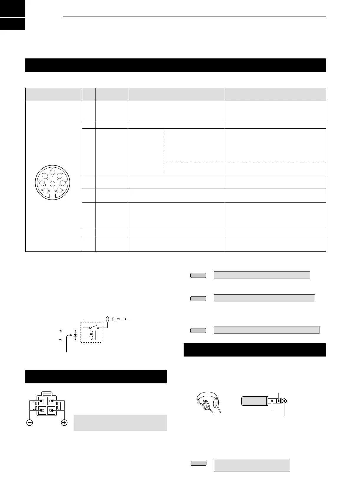
CONNECTOR INFORMATION
[ACC]
Connects to external equipment or a PC to control an external unit or the transceiver.
*
2
You can change the MOD input level.
L100 mV rms is at 50% as the default.
»
SET > Connectors > ACC MOD Level
*
3
You can change the AF/IF
(IF=12 kHz)
settings to output a
12 kHz IF signal. In that case.
»
SET > Connectors > ACC Output Select
*
4
You can change the AF/IF
(IF=12 kHz) output level
.
L Approximately 200 mV rms is at the 50% as the
default.
»
SET > Connectors > ACC IF Output Level
*
1
When the SEND terminal controls an inductive load, such
as a relay, a counter-electromotive force can malfunction
or damage the transceiver. To prevent this, we recommend
adding a switching diode, such as an 1SS133, on the load
side of the circuit to absorb the counter-electromotive force.
When the diode is added, a delay in relay switching may
occur. Be sure to check its switching action before operating.
(Example) ACC socket
To a non-Icom
linear amplier
Relay
Switching diode
e SEND
u 13.8 V
ACC 1
PIN
No�
NAME DESCRIPTION SPECIFICATIONS
1 RTTY Controls RTTY keying.
High level:
Low level:
Output current:
More than 2.4 V
Less than 0.6 V
Less than 2 mA
2 GND Connects to ground. –
3 SEND*
1
Input/output
pin.
An external unit controls
the transceiver.
When this pin goes to
ground, the transceiver
transmits.
Input voltage (RX):
Input voltage (TX):
Current ow:
2 ~ 20 V
–0.5 ~ +0.8 V
Maximum 20 mA
The pin goes low when
the transceiver transmits.
Output voltage (TX):
Current ow:
Less than 0.1 V
Maximum 200 mA
4 MOD
Modulator input.
Connects to the internal modulator circuit.
Input impedance:
Output level:
10 kΩ
Approx. 100 mV rms*
2
5
AF/IF
(IF=12 kHz)*
3
Fixed AF detector or receive IF (12 kHz)
signal output.
Output impedance:
Output level:
4.7 kΩ
100 ~ 300 mV rms
*
4
6 SQL S
Squelch output.
This pin goes to ground when the
squelch opens (TX/RX indicator lights
green).
SQL open:
SQL closed:
Less than 0.3 V/5 mA
More than 6.0 V/100 μA
7 13.8 V 13.8 V output when power is ON. Output current: Maximum 1A
8 ALC ALC voltage input.
Input level:
Input impedance:
–4 ~ 0 V
More than 10 kΩ
8-pin
Rear panel view
1
2
3
4
5
6
7
8
[DC 13�8 V]
Accepts the regulated DC power
for 13.8 V DC ±15% through the
supplied DC power cable.
RWARNING! NEVER reverse the
DC power cable polarity.
Rear panel view
[PHONES]
Connects to standard stereo headphones:
• Output impedance: 8 ~ 16 Ω
• Output level: More than 5 mW into an 8 Ω load.
L The internal speaker is deactivated while an external
speaker is connected.
L When high impedance headphones are used, the audio
output level may be too high.
LYou can change the headphone output setting.
»
SET > Connectors > Phones >
LR/ Mix ACC MOD Level
Main band signal
Sub band signal
3.5 (d) mm (
1
/8 in)
GND

 Loading...