107
12
CONNECTIONS AND MAINTENANCE
Microphone installation ■
The supplied or optional HM-205* and the optional HM-195
should be connected to the transceiver using the connection
cable that comes with the transceiver or the microphone.
The cable is used to operate from a longer distance. The
cable connector can also be installed as a built-in plug on a
cabinet or wall.
*Not supplied with some transceiver versions.
To operate from even longer distances, the optional 6 meter
long OPC-999 or OPC-1541 extension cable can be used be-
tween the transceiver and the OPC-1000 or OPC-1540. Up to
two OPC-999 or OPC-1541 can be added.
•OPC-999: FortheHM-205
•OPC-1541: FortheHM-195
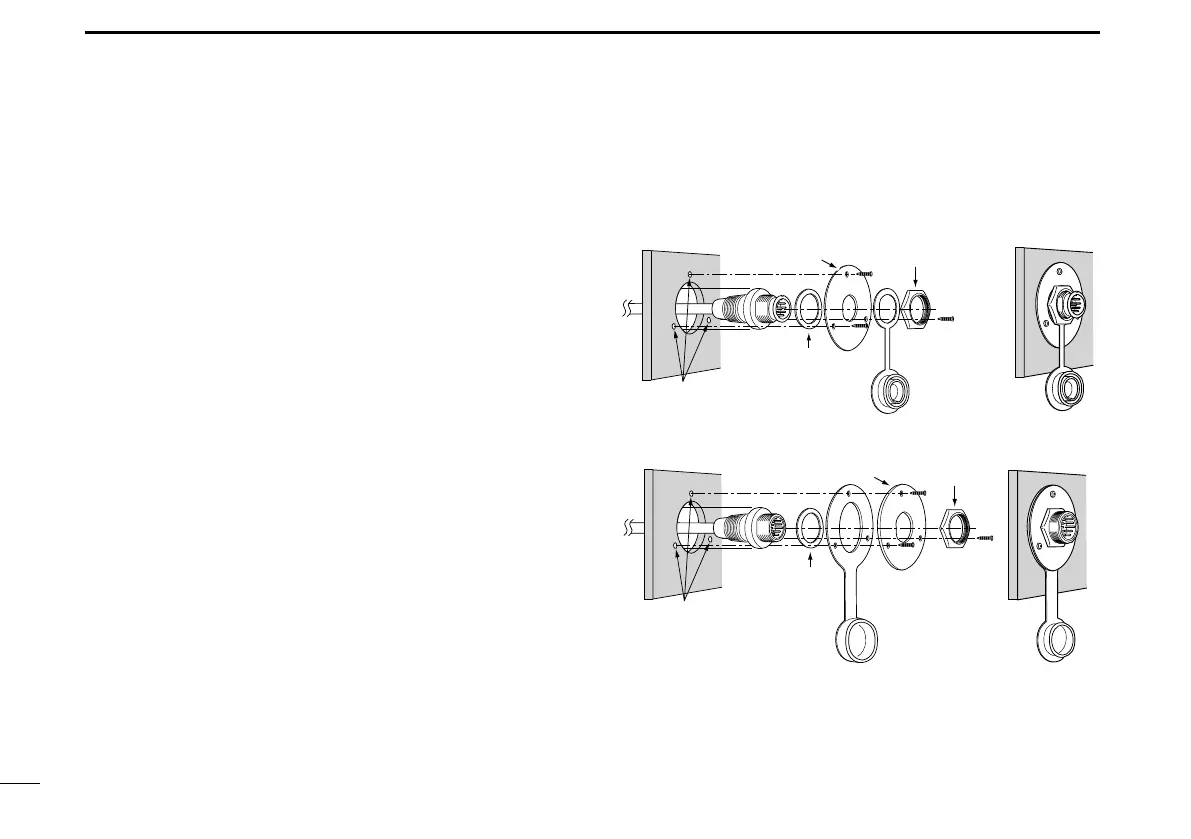
Installation D
Insert the connection cable connector into the microphone q
connector or the command microphone jack, and tighten
the nut.
To use the cable connector as a wall socket, install it as w
described below.
Using the mounting base as a template, carefully mark the e
holes where the cable and three screws will be fastened.
Drill holes at these marks. r
Install the mounting base using the supplied screws, as t
shown below.
• HM-205
• HM-195
Gasket
Cap
Mounting base
Nut
Screw holes
(approximately 2 (d) mm; 0.1 inches)
Gasket
Cap
Mounting base Nut
Screw holes
(approximately 2 (d) mm;
0.1 inches)

 Loading...


