27
4
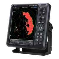
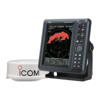
DISTANCE AND DIRECTION MEASUREMENTS
■ Advanced measurements
q Push [p], [q], [t], or [u] to move the cursor onto
the desired target.
w Push [EBL1 (VRM1)]/[ ] to display the
EBL1 and VRM1.
• Push [t] or [u] to rotate the Electronic Bearing Line.
• Push [p] or [q] to increase or decrease the Variable
Range Marker ring size.
e Push [ENTER]/[ ] to set the VRM/EBL1 setting.
r Push [EBL2 (VRM2)]/
[ ]
to display the
EBL2 and VRM2.
• The intersection of the EBL1 and VRM1 becomes the
center of the EBL2 and VRM2.
t Push [p], [q], [t], or [u] to move the cursor onto
the other target.
• Push [t] or [u] to rotate the Electronic Bearing Line.
• Push [p] or [q] to increase or decrease the Variable
Range Marker ring size.
y The VRM2 readout displays the distance between
the two targets. The EBL2 readout displays the di-
rection from one target to the other.
D Measuring the distance and direction between two targets
Using both Electronic Bearing Lines (EBL) and both Variable Range Markers (VRM), the following advanced mea-
surements can be made.
■ Bearing and Distance measurement
This radar has two Electronic Bearing Lines (EBL) to
indicate the target direction from your ship or a target.
D Using both the EBL and VRM
q Push [p], [q], [t], or [u] to move the cursor onto
the desired target.
w Push [EBL1 (VRM1)]/[ ] to display the
EBL1 and VRM1.
• Push [t] or [u] to rotate the Electronic Bearing Line.
• Push [p] or [q] to increase or decrease the Variable
Range Marker’s ring size.
• The EBL/VRM1 readout indicates the target bearing and
distance.
• The EBL readouts indicate the target bearing.
The indication may differ, depending on the setting in the
“Bearing Reference” item of the System menu (p. 12).
0 to 360°R: Relative direction, when “360°R” is se-
lected in the “Bearing Reference” item.
P/S 0 to 180°: Bow direction, when “PT/SB” is selected
in the “Bearing Reference” item.
0 to 360°T*: True or magnetic bearing, when selecting
“True” in the “Bearing Reference” item.
*Bearing data is required. (p. 63)
e Push [ENTER]/[ ] to set the EBL/VRM1 setting.
r Push [p], [q], [t], or [u] to move the cursor onto
the desired target.
t Hold down [EBL1 (VRM1)]/
[ ]
for 1sec-
ond to move the EBL1 and VRM1 to the cursor.
• Hold down [EBL1 (VRM1)]/
[ ]
for 1second
again to move the EBL1 and VRM1 to the original place.
y Push [EBL1 (VRM1)]/[ ] to clear the
EBL1 and VRM1.
• The cursor remains on the display.
EBL1
VRM1
VRM2
EBL2
EBL/VRM1
readout
EBL/VRM1
readout
EBL1
VRM1
VRM1
EBL1
 Loading...