2
1
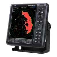
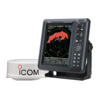
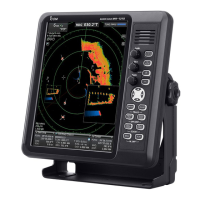
PANEL DESCRIPTION
i
OFF CENTER FUNCTION [OFF CENT]/[ ] (p. 19)
Simultaneously push [MENU]/[ ] and [MODE]/
[ ] to turn the OFF CENTER function ON or OFF.
• This function is usable in the 24 NM or less ranges.
o EBL2 (VRM2) KEY [EBL2 (VRM2)]/
[ ] (pp. 26–28)
➥ Push to display the EBL2 (Electronic Bearing
Line 2) and the VRM2 (Variable Range Marker 2.)
• Push [t] or [u] to adjust the EBL selector, or push
[p] or [q] to adjust the VRM selector. Then push
[ENTER]/[
] to set the point.
• The EBL2 bearing and the VRM2 distance are dis-
played in the lower right corner of the screen.
• When the EBL1 and the VRM1 are displayed, the
center of the VRM2 is displayed at the intersection
point of the EBL1 and the VRM1.
➥
While holding down [EBL1(VRM1)]/[ ],
hold down [EBL2(VRM2)]/[ ]
for 1 sec-
ond to turn the PI (Parallel Index) lines ON or
OFF. (p.26)
!0 ZOOM FUNCTION [ZOOM]/[
] (p. 20)
Simultaneously push [EBL1(VRM1)]/[ ]
and [EBL2(VRM2)]/[ ] to turn the ZOOM
function ON or OFF. The ZOOM function enlarges the
target to two times normal size.
• Move the cursor to the target, then turn ON the function.
• The zoomed area is displayed by the doted square.
!1 ALARM KEY [ALM]/[ ] (p. 29)
➥ Push [ALM]/[ ] to select the Alarm function,
ALM1, ALM2, ALM1 & ALM2, or OFF.
➥ Hold down [ALM]/[ ] for 1 second to enter the
alarm area setting mode.
• Push [p], [q], [t], or [u] to move the cross cursor to
the zone starting point, then hold down [ALM]/[
]
for 1 second. The starting ring of the zone is created.
Then push [p], [q], [t], or [u] to fix the finish point,
and then push [ALM]/[
]. The desired alarm zone
will automatically form.
!2 HEADING LINE OFF FUNCTION [HL OFF]/
[ ] (p. 16)
While holding down [BRILL]/[ ] and [ALM]/
[ ], the heading line is temporarily turned OFF.
• The rings or other objects can also be turned OFF when the
“HL OFF Mode” item in the System menu is set to “All.” (p. 11)
!3
DISPLAY BRILLIANCE KEY [BRILL]/[ ] (p. 17)
➥
Push to display the Brilliance/Color setting box.
• The key backlight can be adjusted in this setting box.
• The brightness of the symbols, characters and illumina-
tions can be independently adjusted in the Color menu.
➥ Push to increase or decrease the brilliance of the
picture on the display.
➥ Hold down for 1 second to select maximum bril-
liance.
!4 EBL1 (VRM1) KEY [EBL1 (VRM1)]/
[
] (pp. 26–28)
➥
Push to display the EBL1 (Electronic Bearing
Line 1) and the VRM1 (Variable Range Marker 1.)
• Push [t] or [u] to adjust the EBL selector, or push
[p] or [q] to adjust the VRM selector. Then push
[ENTER]/[
] to set the point.
• The EBL1 bearing and the VRM1 distance are dis-
played in the lower left corner of the screen.
• When the EBL1 and the VRM1 are displayed, the
beginning of the EBL2 is displayed at the intersection
point of the EBL1 and the VRM1.
➥
While holding down [EBL1(VRM1)]/[ ],
hold down [EBL2(VRM2)]/[ ]
for 1 sec-
ond to turn the PI (Parallel Index) lines ON or
OFF.
(p.26)
!5 MENU KEY [MENU•TLL]/[ •TLL]
➥ Push to enter or exit the Menu screen. (pp. 5–14)
• Push [t] or [u] to select the Menu groups, or push
[p] or [q] to select the items.
➥ Hold down for 1 second to output the position
information where the cursor is placed, to the
NMEA output terminals. (p. 52)
• TLL output requires bearing data and position data.
• The target mark can be displayed, depending on the
setting in the “TLL Mode” item of the System menu.
(p. 11)
!6 ENTER KEY [ENTER]/[ ]
➥ Push to set the ATA, AIS, TLL, or WPT target to
the selected mode. (pp. 23, 32, 37)
➥ In the Menu screen, push to enter the Submenu
or Option selection mode, or push to save the
setting. (p. 5)
➥ Hold down for 1 second to turn the sleeping AIS
target into an activated target. (p. 38)
• Hold down [CLEAR]/[ ] for 1 second to change
the activated AIS target to a sleeping target.
!7
RAIN CLUTTER CONTROL [RAIN]/[ ] (p. 18)
Eliminates echoes from rain, snow, fog, and so on.
Rotate the control fully counter clockwise to deacti-
vate the RAIN function.
• The RAIN icon ( ) disappears.
!8
SEA CLUTTER CONTROL [SEA]/[ ] (p. 18)
Eliminates echoes from waves in close range.
Reduces the receiver gain for close objects within a
radius of approximately 8 nautical miles to eliminate
sea clutter.
Rotate the control fully clockwise to activate the au-
tomatic SEA control function.
•
The SEA icon ( ) is displayed in the upper left of the screen.
• “AUTO” is displayed below the SEA icon ( ) when the
automatic control function is active.
• Under normal conditions set the SEA to minimum.
• Use this control with caution when the sea is rough.
!9 GAIN CONTROL [GAIN]/[ ] (p. 16)
Adjusts the receiver amplifier gain.
• Clockwise rotation increases the gain.
• The increased gain may increase screen noise.
 Loading...