INSTALLATION
Ideal Logic Code Combi - Installation and Servicing
32
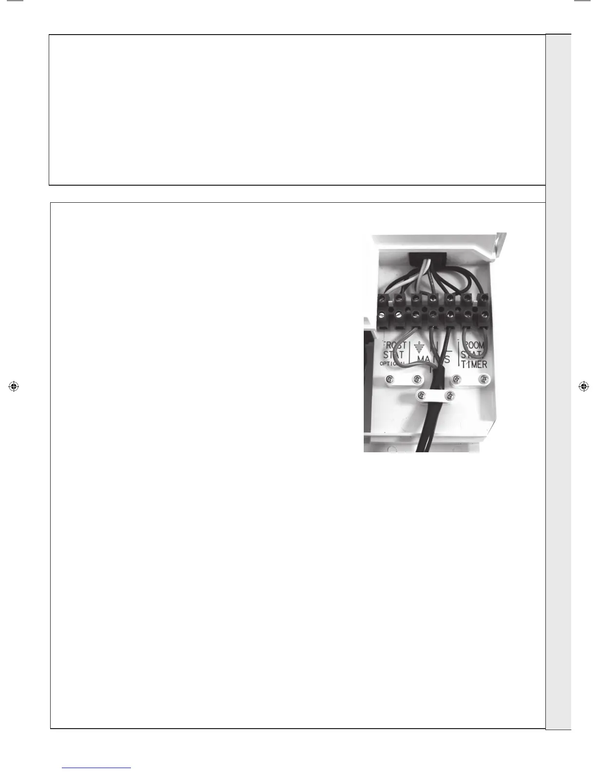
INTERNAL WIRING
a permanent call for heat and must be removed when adding a room
1.
2.
3.
4. Route incoming cables through the grommets in bottom panel (note,
5.
6.
Ideal offer 4 kits as follows:
(see individual kits for installation instructions)
Mechanical Timer (24 hr) Kit - 24 hour mechanical CH
Electronic Timer (7 day) kit - 7 day electronic CH timer
RF Mechanical Programmable Room Thermostat (24
hr) kit - Combined 24 hour mechanical timer and room
thermostat with wireless communication to receiver unit
RF Electronic Programmable Room Thermostat (7
day) kit - Combined 7 day timer and room thermostat
ROOM THERMOSTAT (NO TIMER) - WIRING
1.
2. Connect room stat across terminals as shown in diagram A -
3. If room stat has a neutral connection, connect this to terminal
ROOM THERMOSTAT + TIMER - WIRING
1.
2. Connect room stat and programmer in series as shown in
3. If room stat has a neutral connection, connect this to terminal
FROST THERMOSTAT - WIRING
If parts of the system are vulnerable to freezing or the
programmer is likely to be left off during cold weather, a frost stat
1.
2. Connect frost stat across terminals marked frost stat as
31
ELECTRICAL CONNECTIONS
2
Connection must be made in a way that allows complete
isolation of the electrical supply such as a double pole switch
means of isolation must be accessible to the user after
WARNING
INSTALLATION
206279-1.indd 29 06/01/2011 09:10:18