EasyManua.ls Logo

Ideal Boilers LOGIC Code Combi 26 - Wall Mounting Template; Preparing the Wall

Ideal Boilers LOGIC Code Combi 26
64 pages
Print Icon
To Next Page IconTo Next Page
To Previous Page IconTo Previous Page
Loading...

INSTALLATION
Ideal Logic Code Combi - Installation and Servicing



Note.
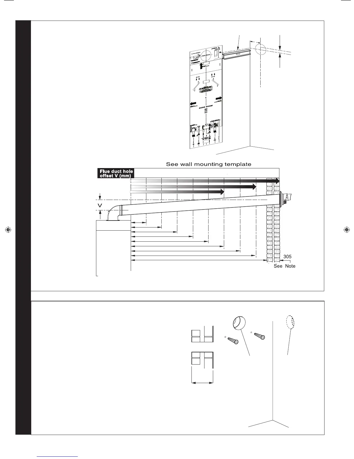
The template shows the positions of the xing holes and the
rear ue hole centre for standard installation. Care MUST be
taken to ensure the correct holes are drilled.
1. 

2. 

3. Mark onto the wall the following:
a 

b.
Note. Mark the centre of the hole as well as the
circumference.
4. 
13
WALL MOUNTING TEMPLATE
14
PREPARING THE WALL
IMPORTANT.
Ensure that, during the cutting operation, masonry falling
outside of the building does not cause damage or personal

1. 

Both wall faces immediately around the cut hole should be

2. 

3. 
(one at each side, in any of the 3 holes provided at each

3G9495
X
Section
through wall
Note. Check all of the hole
positions before drilling.
Side flue only
5" diameter hole
Rear flue only
5" diameter hole
206279-10258
31 57 83 109 135 161 187 213
239
1.0
2.0
3.0
4.0
5.0
6.0
7.0
8.0
8.5
Notes.
1. If the wall thickness is greater than 305mm then dimension "H"* must
be reduced by the same amount and the offset may be adjusted accordingly.
2. For flue lengths greater than 600mm the flue must be inclined by 26mm per 1000mm flue length.
* "H" = Distance in metres from side of the boiler to the side wall
code combi 38
code combi 33
code combi 26
206279-10271
V - See Diagram Below
Extended centre line
155
206279-1.indd 18 06/01/2011 09:09:59

Related product manuals