INSTALLATION
Ideal Logic Code Combi - Installation and Servicing
16
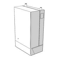
SETTING THE FLUE - REAR
Notes.
a. If using the extension ducts go to Frame 18.
b. For shorter ue requirements use non telescopic B
Pack.
c. If the stand-off Frame is used it is essential to add
45mm to ‘X’ the measured wall thickness when marking
the ue (this will allow for the tted Frame).
1.
2.
3.
4.
5.
nm8944
X + 75
Drill hole
Adhere sealing tape
Measurement to be
taken from this point
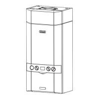
NON TELESCOPIC FLUE - Wall thickness of 115mm to 485mm
TELESCOPIC FLUE - Wall thickness of 195mm to 420mm
Notes.
a. If using the extension ducts go to Frame 18.
b. If the stand-off Frame is used it is essential to add 45mm
to ‘X’ the measured wall thickness when marking the ue
(this will allow for the tted Frame).
1.
2.
3.
4. Cut the inner tube to a length 20mm longer to aid
Measure from
this
RING
3G9675
15
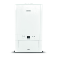
TERMINAL WALL SEAL ASSEMBLY / POSITIONING
Ensure lip of wall seal is positioned
over step on plastic nose of flue terminal
(note, seal is cut away for clarity)
Step
isfu9783
Wall Seal Lip
FIGURE 1 FIGURE 2
that the rubber
terminal wall seal is pressed against the outside wall to create
206279-10259
Rubber
Terminal
Wall Seal
206279-1.indd 19 06/01/2011 09:10:01