Ensure that the guard is tted centrally.
The air inlet/products outlet duct and the terminal of the boiler
MUST NOT be closer than 25mm to combustible material. Detailed
recommendations on the protection of combustible material are
given in BS. 5440-1: 2008. In IE refer to I.S.813:2002.
The ue must be installed in accordance with Building Regulations
and the recommendations of BS. 5440-1:2008 for inputs up to
70kW nett. For larger installation BS. 6644 should be complied
with. In IE refer to I.S.820:2000.
1.9 WATER CIRCULATION SYSTEM
The system pump MUST be connected to the boiler, see below.
The boiler must NOT be used for direct hot water supply. The hot
water storage cylinder MUST be of the indirect type.
Single feed, indirect cylinders are not recommended and MUST
NOT be used on sealed systems.
The appliances are NOT suitable for gravity central heating nor
are they suitable for the provision of gravity domestic hot water.
The hot water cylinder and ancillary pipework, not forming part of
the useful heating surface, should be lagged to prevent heat loss
and any possible freezing - particularly where pipes run through
roof spaces and ventilated underoor spaces.
The boiler must be vented.
Draining taps MUST be located in accessible positions, which
permit the draining of the whole system - including the boiler
and hot water storage vessel. They should be at least 1/2” BSP
nominal size and be in accordance with BS. 2879.
The central heating system should be in accordance with the
relevant standards listed on page 8.
Due to the compact nature of the boiler the heat stored within the
castings at the point of shutdown of the burner must be dissipated
into the water circuit in order to avoid overheating. In order to
allow pump operation after burner shutdown the boiler control box
incorporates a 4 minute pump overrun facility. In order to make use
of this, the pump must be supplied from the terminals inside the
boiler. Note: for pumps requiring a current greater than 1.3 amps
inductive, they must be connected via a relay.
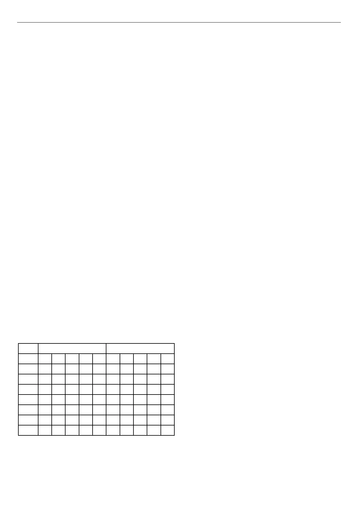
When sizing pumps, reference should be made to the table below
which show the boiler resistance against ow rates, to achieve the
required temperature differential.
Flow rates for common systems using either 11ºC, 15ºC, 20ºC,
25ºC and 30ºC temperature differentials and hydraulic resistances
are given in the table below
Flowrate (l/min) Hydraulic Resistance (mbar)
11ºC 15ºC 20ºC 25ºC 30ºC 11ºC 15ºC 20ºC 25ºC 30ºC
30/30P 39.1 28.7 21.5 17.9 N/A 425 225 127 89 N/A
40/40P 52.1 38.2 28.7 23.9 19.1 875 405 225 163 100
60/60P 78.2 57.3 43 35.9 28.7 435 180 83 57 30
80/80P 104.2 76.4 57.3 47.8 38.2 750 420 180 125 70
100/100P
* 95.6 71.7 59.8 47.8 * 315 134 97 60
120/120P
* * 86 71.7 57.3 * * 218 149 80
150 * * 107.5 89.6 71.7 * * 230 158 85
* Not recommended due to excessive owrates which may cause
erosion of the casting.
Note.
•
With the boiler ring at maximum rate, the temperature
differential should not be less than gures quoted in table above.
High ow rates required for lower temperature differentials could
lead to erosion of the heat exchanger water ways.
• With the boiler ring at minimum rate, the temperature
differential should not be greater than 35
o
C. Lower ow rates
generating higher temperature differentials will lead to lock out
of the boiler.
• The lower the return temperature to the boiler, the higher the
efciency.
In installations where all radiators have been provided with
thermostatic radiator valves, it is essential that water circulation
through the boiler is guaranteed. This can be best achieved
by means of a differential pressure valve, which is installed in a
bypass between the ow and return pipes. The bypass should
be tted at least 6m from the boiler, and should use a minimum
size of 28mm pipe. The bypass should be capable of allowing
a minimum ow rate to achieve a temperature differential of no
greater than 35
o
C at minimum rate.
1.10 WATER TREATMENT
These boilers incorporate an ALUMINIUM heat exchanger.
IMPORTANT. The application of any other treatment to this
product may render the warrnaty of Ideal Boilers INVALID.
Ideal Boilers recommend Water Treatment in accordance with
Guidance Notes on Water Treatment in Central Heating Systems.
If water treatment is used Ideal Boilers recommend only the
use of
SCALEMASTER SM-1 PRO, FERNOX, MBI, ADEY MC1,
SENTINEL X100 or CALMAG CM100 inhibitors and associated water
treatment products, which must be used in accordance with the
manufacturers’ instructions.
For further information contact:
Fernox
www.fernox.com
Tel: +44 (0) 3301 007750
Sentinel Performance Solutions
www.sentinelprotects.com
Tel: +44 (0) 1928 704330
Scalemaster Water Treatment Products
www.scalemaster.co.uk
Tel: +44 (0) 1785 811636
Calmag Ltd.
www.calmagltd.com
Tel: +44 (0) 1535 210320
Adey
www.adey.com
Tel: +44 (0) 1242 546700
Notes.
1. It is most important that the correct concentration of the water
treatment products is maintained in accordance with the
manufacturers’ instructions.
2. If the boiler is installed in an existing system any unsuitable
additives MUST be removed by thorough cleansing.
3. In hard water areas, treatment to prevent lime scale may be
necessary - however the use of articially softened water is
NOT permitted.
4. Under no circumstances should the boiler be red before the
system has been thoroughly ushed.
10
Installation & Servicing
SECTION 1 - GENERAL

 Loading...