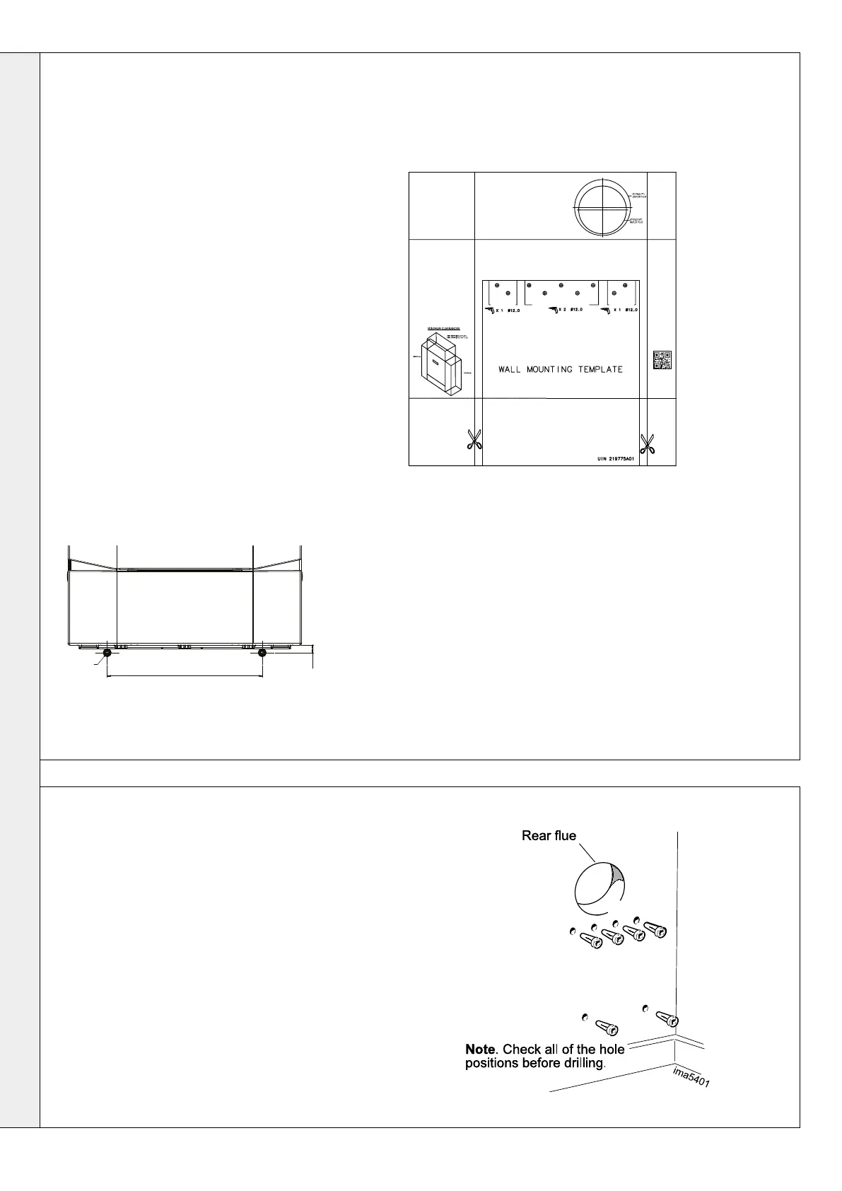
2.4 WALL MOUNTING TEMPLATE
2.5 PREPARING THE WALL
Note. The template shows the positions for the
top xing holes. Care must be taken to ensure
the correct holes are drilled.
1. Tape template into the selected position.
2. Ensure squareness by hanging a plumbline.
3. Mark on to the wall:
a. The top 4 wall mounting plate screw
positions.
b. The 2 boiler lower xing positions using
diagram below
c. The position of the ue duct. Mark
the centre of the hole as well as the
circumference.
4. Remove the template from the wall.
IMPORTANT. The wall must be vertical 90º (±5º)
from the perpendicular to allow safe operation of
the integral ue non return valve.
Ensure that, during the cutting operation, masonry
falling outside of the building does not cause
damage or personal injury.
1. Cut the ue hole ensuring that the hole
is square to the wall. Both wall faces
immediately around the cut hole should be at.
2. Drill 4 boiler top xing holes with a 12mm
masonry drill and insert the plastic plugs
provided, for the wall mounting plate.
3. Drill the 2 boiler lower xing holes with a 12mm
masonry drill, insert the plastic plugs provided .
4. Fix the wall bracket into place with 4 M10x70
hex head coach screws provided.
Note: Horizontal ue runs must be
inclined at 1.5-3
o
to the horizontal to allow
condensate to drain back to the boiler.
BOILER LOWER FIXING POSITIONS
mm332
Ø12mm
850mm to top of boiler
mm17
B
16
Installation & Servicing
SECTION 2 - INSTALLATION
INSTALLATION

 Loading...