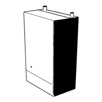
3.14 REMOVAL OF AUTOMATIC AIR VENT
1. Refer to Section 2.33.
2. Remove the front panel. Refer to Section
3.2.
3. Unscrew the air vent (A) from the self
sealing tting (B) on the top left of the ow
pipe.
4. Remove the clear tubing from the air vent
spigot.
5. Fit the new air vent.
6. Ret the clear plastic drain tubing ensuring
there are no kinks as air in the boiler could
cause damage to the heat exchanger.
7. Re-assemble in reverse order.
8. Check the operation of the boiler. Refer to
Section 2.33.
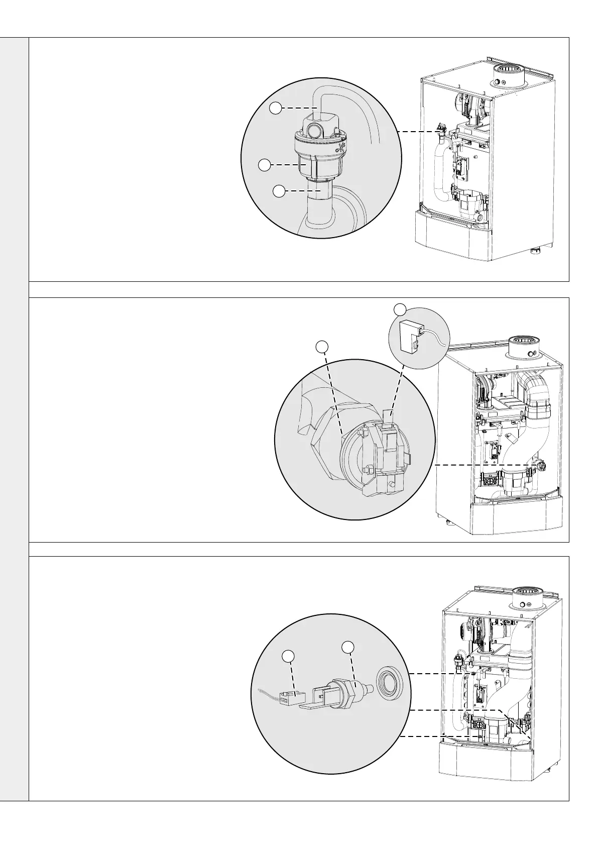
3.15 REMOVAL OF WATER PRESSURE SWITCH
1. Refer to Section 2.33.
2. Remove the front panel. Refer to Section 3.2.
3. Isolate the water circuit and drain the boiler.
4. Disconnect the electrical connections from the switch.
5. Unscrew the water pressure switch.
6. Ret new switch.
7. Connect electrical connections.
8. Rell the system ensuring all the air escapes via the
air vent.
9. Reassemble in reverse order.
10. Check the operation of the boiler. Refer to Section
2.33.
3.16 REMOVAL OF FLOW / RETURN / HEAT EXCHANGER THERMISTOR
1. Refer to Section 2.33.
2. Remove the front panel. Refer to Section 3.2.
3. Isolate the water circuit and drain the system.
4. Disconnect the electrical connections from the
thermistor.
5. Unscrew the thermistor.
6. Fit the new thermistor and seal. Do not
overtighten.
7. Rell the system ensuring all the air in the
heat exchanger is vented through the air vent.
8. Re-assemble in reverse order.
9. Check the operation of the boiler. Refer to
Section 2.33.
HX
Return
Flow
A
4
B
4
x2
5
4
5
58
Installation & Servicing
SECTION 3 - SERVICING
SERVICING

 Loading...