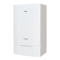
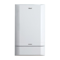
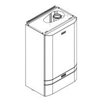
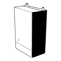
1.13 BOILER CLEARANCES AND CONNECTIONS
The following minimum clearances must be
maintained for operation and servicing.
Front of boiler - 450mm
Sides of boiler - 25mm
Above boiler - dependent upon the ue
system see drawings
Below boiler - 300mm
Clearance between multiple boiler
installations - 25mm
80/125 CONCENTRIC FLUE CONNECTOR
30, 40, 60 & 80
Minimum boiler top clearances:
for vertical ue 200mm
for horizontal ue 350mm (415mm for 100/150)
for open ue 350mm
100/150 CONCENTRIC FLUE CONNECTOR
100, 120 & 150
Minimum boiler top clearances:
for vertical ue 200mm
for horizontal ue 370mm
for open ue 350mm
Flue centre
line
=194.5 (80/125)
=259.5 (100/150)*
* with 100/150 adaptor
(See Frame 13)
FLOW &RETURN CONNECTIONS
81
GAS & CONDENSE OUTLETS
68
B
500
59
59
209
299
A
118
850
RETURN
GAS
CONDENSE
FLOW
Boiler Dim. A Dim. B
30, 40, 60, 80 360 130
100, 120 520 226
150 610 233
OPEN FLUE KIT
100 / 150
OPEN FLUE KIT
80 / 125
ima5400
X
Y
26 52 78 104
Vertical Offset From X mm
Distance from flue centre line (Y) to outside wall surface.
For lengths greater than 4m, increase offset (X) by 26mm
for every additional 1m.
4m
3m
2m
1m
100
83
148.5
80
83
125
12
Installation & Servicing
SECTION 1 - GENERAL

 Loading...


