1.
Note: Ensure condensate trap is
fully drained before removal.
2.
3. Disconnect the condensate
4.
5.
6. When reassembling ensure
7.
53
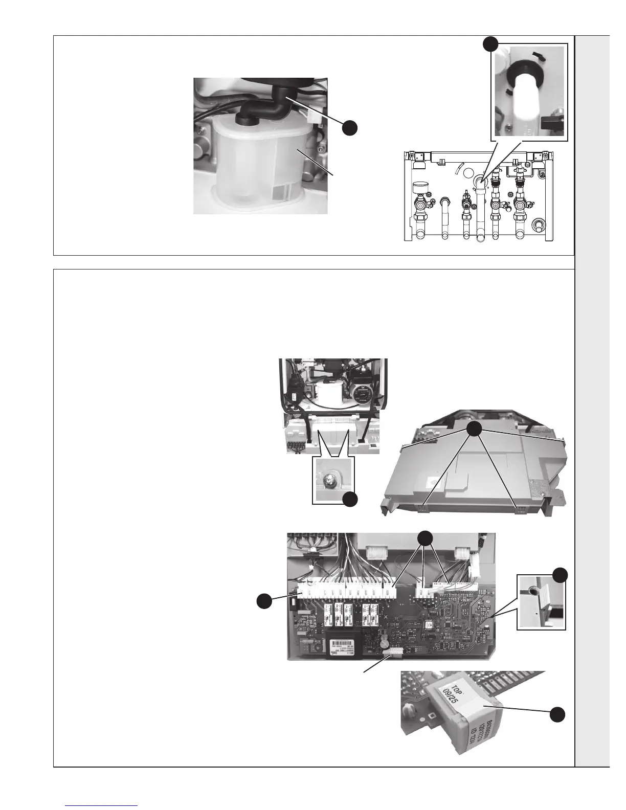
CONDENsa TE TRap/sIphON REpLaCEMENT
54
MaIN pCB REpLaCEMENT
Note. Fit the earth strap provided with the PCB to
your wrist and secure to a suitable earth on the
boiler chassis.
1.
2.
3. Remove the 2 screws retaining the control box
4. Carefully lift the 4 retaining clips and remove
5.
including the ribbon cable (to facilitate ribbon
cable removal, ease side clips apart and pull
upwards), also where applicable, push the
small plastic clip with an electrical screwdriver
6.
7.
appropriate Boiler Chip Card (BCC) to it (this
should correspond to the output of the boiler:
Note.
Ensure the correct orientation of BCC by
placing “TOP” side up as shown.
8.
9.
10. a.
b.
c. Move knob to required setting (standby,
summer, winter)
Note. If no BCC tted on non programmed
board items a & b will be displayed then
“Boiler
Type Card Fault - Contact Installer” The correct
BCC for this appliance will need to be tted.
11.
3
3
4
5
Clip
5
2
Ribbon
Cable
Connection
7
Note that production boiler PCBs are factory pre-set to operate for boiler range and output, but when ordering Primary PCB as a
spare, an additional Boiler Chip Card (BCC) MUST also be purchased for your specic boiler range and output.
sERVICINg