FC6A S
ERIES
MICROS
MART
U
SER
’
S
M
ANUAL
FC9Y-B1722 2-111
2: P
RODUCT
S
PECIFICATIONS
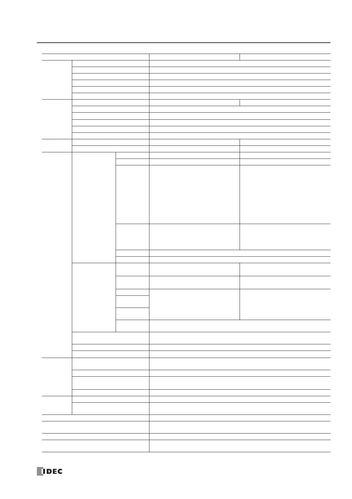
*1 The resistance (allowable conductor resistance) of the electrical leads to connect to the resistance thermometer is 10 Ω or less per wire.
Input
Impedance
Voltage 1 MΩ or higher
Current 50 Ω or lower
Thermocouple 1 MΩ or higher
Resistance Thermometer 1 MΩ or higher
Thermistor 1 MΩ or higher
Resistor 1 MΩ or higher
AD
Conversion
Sampling Time 1 ms or 10 ms 10 ms, 100 ms, or 104 ms
Sampling Repetition Time Sampling time × Number of enabled input channels
Total Input Delay Time
*2
Sampling time + Sampling repetition time + 1 scan time
Type of Input Single-ended
Operation Mode Self-scan
Conversion Method Σ∆ type ADC
Input Error
Maximum Error at 25°C ±0.2% of full scale ±0.1% of full scale
Temperature Coefficient 0.01% of full scale/°C 0.006% of full scale/°C
Data
Digital Resolution
Voltage 4,096 (12 bits) 65,536 (16 bits)
Current 4,096 (12 bits) 65,536 (16 bits)
Thermocouple
―
K: 15,000 (14 bits)
J: 12,000 (14 bits)
R: 17,600 (15 bits)
S: 17,600 (15 bits)
B: 18,200 (15 bits)
E: 10,000 (14 bits)
T: 6,000 (13 bits)
N: 15,000 (14 bits)
C: 23,150 (15 bits)
Resistance
Thermometer
―
Pt100: 10,500 (14 bits)
Pt1000: 8,000 (13 bits)
Ni100: 2,400 (12 bits)
Ni1000: 2,400 (12 bits)
Thermistor ―
Resistor ―
Input Value per
Step
Voltage
2.44 mV (0 to 10 V)
4.88 mV (-10 to +10 V)
0.15 mV (0 to 10 V)
-0.30 mV (-10 to +10 V)
Current
4.88 μA (0 to 20 mA)
3.91 μA (4 to 20 mA)
0.30 μA (0 to 20 mA)
0.244 μA (4 to 20 mA)
Thermocouple
― 0.1°C or 0.18°F
Resistance
Thermometer
Thermistor
(NTC)
Thermistor
(PTC)
―
Data Type in Application
Program
Can be arbitrarily set for each CH in a range between -32,768 to 32,767
*3
Monotonicity Yes
Input Data Out of Range
Detectable
*4
Noise
Resistance
Maximum Temporary Deviation
during Electrical Noise Tests
±4% or less of full scale
Input Filter Yes
Recommended Cable
for Noise Immunity
Current/voltage: Pair shielded cable Wire length: 30 m or shorter
Other: Pair cable Wire length: 30 m or shorter
Crosstalk 1 LSB or lower
Isolation
Between Input and Power Circuit
Transformer isolated
Between Input and Internal
Circuit
Photocoupler isolated
Effect of Improper Input Connection No damage
Maximum Permanent Allowed Overload (No
Damage)
30V DC, 160mA or lower
*5
Selection of Input Type and Input Range Using programming software
Calibration or Verification to Maintain Rated
Accuracy
Not possible
Type No. FC6A-L06A1, FC6A-L06A4 FC6A-L03CN1, FC6A-L03CN4

 Loading...