2: P
RODUCT
S
PECIFICATIONS
2-110 FC6A S
ERIES
MICROS
MART
U
SER
’
S
M
ANUAL
FC9Y-B1722
*1 The resistance (allowable conductor resistance) of the electrical leads to connect to the resistance thermometer is 10 Ω or less per wire.
*2 The total input delay time increases in proportion to the number of channels used. Input channels that have been set to unused are not
included in the number of enabled input channels.
*3 FC6A-J8A1 and FC6A-J8A4 (Version lower than 200) supports 4096 (12 bits) digital resolution.
The input values per step are as follows:
Voltage: 2.44 mV (0 to 10 V), 4.88 mV (-10 to +10 V)
Current: 4.88 μA (0 to 20 mA), 3.91 μA (4 to 20 mA)
When using FC6A-J8A1/FC6A-J8A4 (Version 200 or later), the digital resolution can be selected from 12 bits or 16 bits in Analog I/O Module
Configuration dialog box in WindLDR.
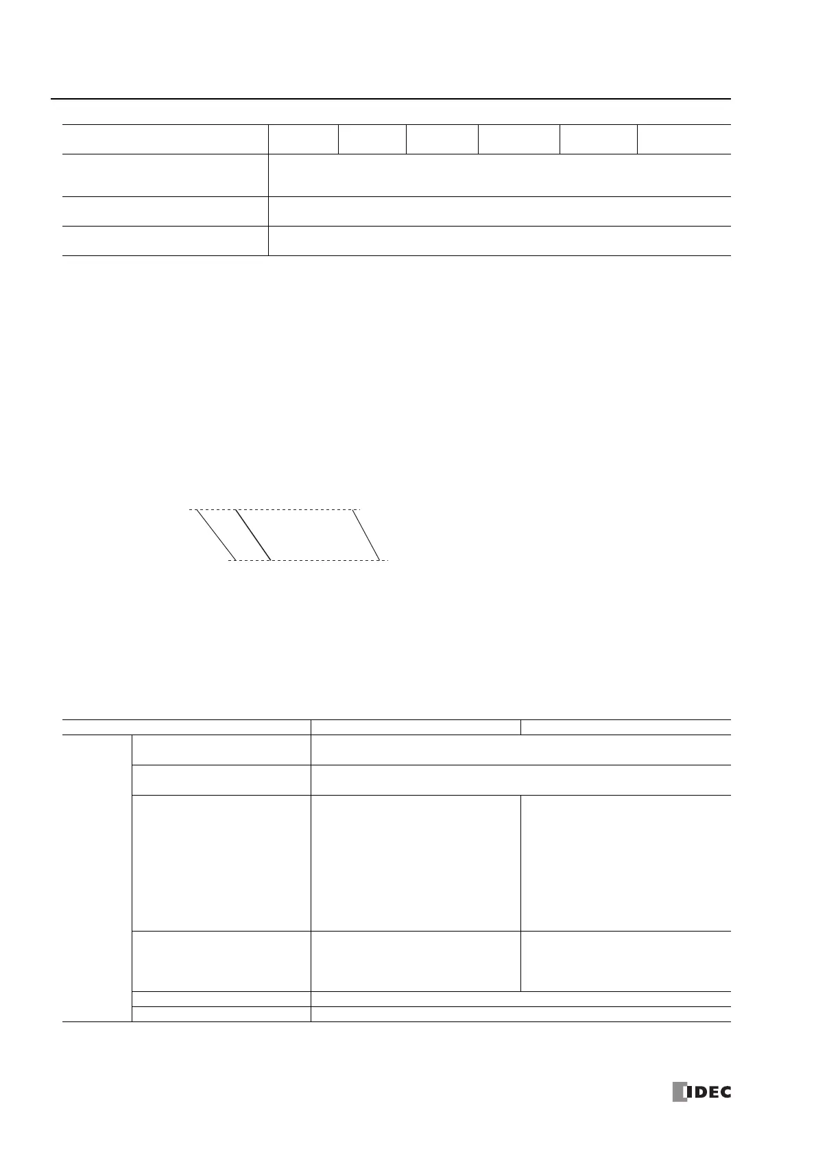
*4 The arbitrary setting is a function that uses the digital resolution data by scaling it to arbitrary data (that arbitrarily sets the lower limit value and
the upper limit value). The range setting (-32,768 to 32,767) is specified with data registers.
Example: When -5 V is input, 1,024 is displayed as long as the arbitrary setting is not configured, but -500 is displayed when the arbitrary
setting is configured as upper limit value = 1,000 and lower limit value = -1,000, and this makes it easier to intuitively read the input
voltage value.
*5 Input data out of range is reflected in the status of the analog I/O module.
*6 For products with a version lower than 200, the maximum permanent allowed overload is 13V DC (when the voltage input is set) and 40mA DC
(when the current input is set). If a current of 160mA or higher (at an ambient temperature of 25°C) flows through the circuit, the protection
function for the input circuit starts operating and works to reduce the applied current. However, the circuit will be damaged if the applied
current is due to voltage applied at 30V DC or higher. For details on the version number of modules, see "Checking the Version Number" on
page 2-1.
Mixed Analog I/O Module
Maximum Permanent Allowed
Overload
(No Damage)
30V DC, 160mA or lowe
*6
Selection of Input Type and Input
Range
Using programming software
Calibration or Verification to Maintain
Rated Accuracy
Not possible
Type No. FC6A-L06A1, FC6A-L06A4 FC6A-L03CN1, FC6A-L03CN4
Input Type
and
Input Range
Voltage
0 to 10 V
-10 to 10 V
Current
4 to 20 mA
0 to 20 mA
Thermocouple ―
(K) -200 to 1,300°C (-328 to 2,372°F)
(J) -200 to 1,000°C (-328 to 1,832°F)
(R) 0 to 1,760°C (32 to 3,200°F)
(S) 0 to 1,760°C (32 to 3,200°F)
(B) 0 to 1,820°C (32 to 3,308°F)
(E) -200 to 800°C (-328 to 1,472°F)
(T) -200 to 400°C (-328 to 752°F)
(N) -200 to 1,300°C (-328 to 2,372°F)
(C) 0 to 2,315°C (32 to 4,199°F)
Resistance Thermometer
*1
―
Pt100: -200 to +850°C (-328 to 1,562°F)
Pt1000: -200 to +600°C (-328 to 1,112°F)
Ni100: -60 to +180°C (-76 to 356°F)
Ni1000: -60 to +180°C (-76 to 356°F)
Thermistor ―
Resistor ―
Type No.
FC6A-J2C1
FC6A-J2C4
FC6A-J4A1
FC6A-J4A4
FC6A-J8A1
FC6A-J8A4
FC6A-J4CN1
FC6A-J4CN4
FC6A-J4CH1Y
FC6A-J4CH4Y
FC6A-J8CU1
FC6A-J8CU4
Lower Limit Value=-1,000 -500
Raw Input Value
Input Voltage Value
1,024
-5 V
4,095
10 V
0
-10 V
Upper Limit Value=1,000
When the digital resolution data is 12 bits and the input range is -10 to +10 V

 Loading...