2: P
RODUCT
S
PECIFICATIONS
2-136 FC6A S
ERIES
MICROS
MART
U
SER
’
S
M
ANUAL
FC9Y-B1722
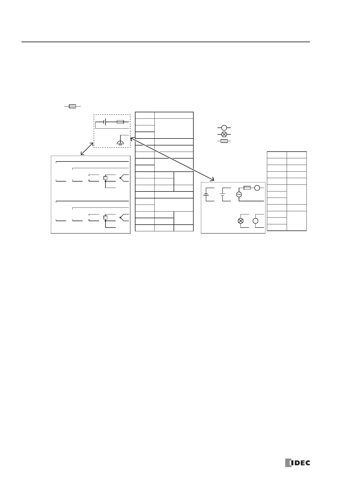
Precautions when Supplying Power to the PID Module
When the PID module and the CPU module are set to the same power supply, the PID module will be initialized for a maximum of
approximately 5 seconds after the power is turned on and the CPU module is set to run, so the parameters will not be stable.
Always enable control after the module status flag changes to "0001H" (operating normally).
Wiring PID Module Power and I/O Lines
Separate I/O lines (resistance thermometers in particular) from power lines as much as possible to reduce the effect of noise.
+
–
L
+–
+
–
TC
A
RTD
B
B’
+
–
0 to 1 V
DCDC
0 to 5 V
1 to 5 V
0 to 10 V
+
–
+
–
DC
0 to 20 mA
4 to 20 mA
+
–
TC
A
RTD
B
B’
+
–
0 to 1 V
DCDC
0 to V
1 to 5 V
0 to 10 V
+
–
+
–
DC
0 to 20 mA
4 to 20 mA
DC
RTD
TC
L
L
: Fuse (50 V-1.2 A) : Voltage/current
: Resistance Thermometer
: Thermocouple
: Load
: Analog Current Input Device
: Fuse
24V
0V
FE
NC
NC
NC
I0+”
I0+’
I0+
I0–
NC
I1+”
I1+’
I1+
I1–
Terminal No.
I/O
24V DC
IN 1
IN 0
NC
NC
NC
NC
NC
IN 0
NC
NC
IN 1
NC
B
B’
A
B
B’
A
Separate power lines and
I/O lines as much as possible.
Separate power lines and
I/O lines as much as possible.
NC
NC
Terminal No.
I/O
OUT 1
Q0–
Q0+
NC
NC
NC
NC
NC
Q1–
Q1+
OUT 0
NC
NC
NC
NC
NC

 Loading...