FC6A S
ERIES
MICROS
MART
U
SER
’
S
M
ANUAL
FC9Y-B1722 2-135
2: P
RODUCT
S
PECIFICATIONS
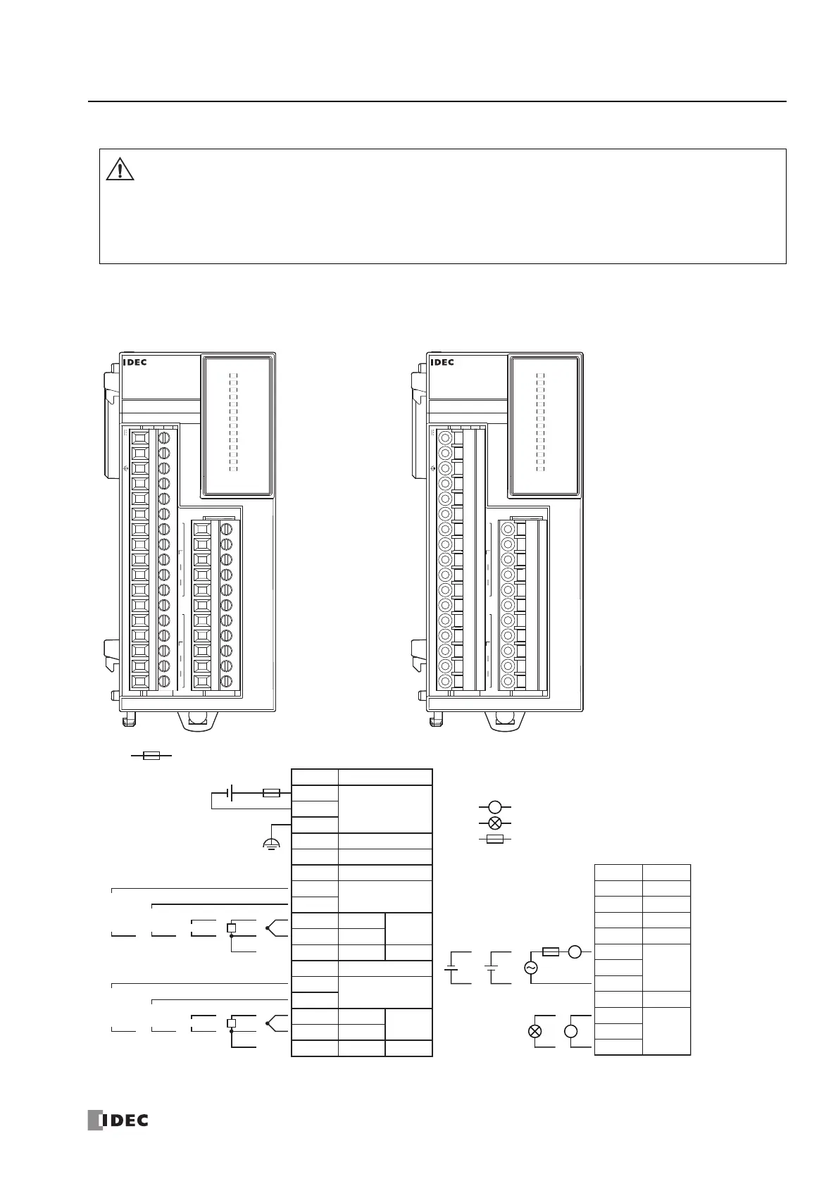
Terminal Arrangement and Wiring Examples
■ FC6A-F2M1, FC6A-F2M4, FC6A-F2MR1, FC6A-F2MR4
*1 OUT0: Relay output and OUT1: Non-contact voltage/current output connection examples are shown. There are no models with both types of
specifications.
When connecting the terminal, insert an IEC 60127-approved fuse suitable for the applied voltage and current draw at
the position shown in the following diagram.
This is required when equipment containing the MICROSmart is destined for Europe.
Do not connect a thermocouple to a part with hazardous voltage (60V DC or peak 42.4V DC or higher part).
Before turning on the power, always check the wiring. If the wiring is incorrect, the PID module may be damaged.
When connecting stranded wire or multiple wires to a terminal block, always use a ferrule for the terminal block.
For details, see "Recommended Ferrule List" on page 3-46.
Screw fastened type: FC6A-F2M1, FC6A-F2MR1 Push-in type: FC6A-F2M4, FC6A-F2MR4
Applicable connector: FC6A-PMTC11PN02
FC6A-PMTC17PN02
Applicable connector: FC6A-PMSC11PN02
FC6A-PMSC17PN02
FC6A-F2M1
NC I1- I1+ I1+’ I1+’’ NC NC I0- I0+ I0+’ I0+’’ NC NC NC 0V 24V
Q1- NC Q1+ NC Q0- NC Q0+ NC NC NC NC
B’ B A RTD B’ B A RTD
OUT0
EVT0
AT0
MT0
F/P0
R/H0
R/L
OUT1
EVT1
AT1
MT1
F/P1
R/H1
PWR
PID
FC6A-F2M4
NC I1- I1+ I1+’ I1+’’ NC NC I0- I0+ I0+’ I0+’’ NC NC NC 0V 24V
Q1- NC Q1+ NC Q0- NC Q0+ NC NC NC NC
B’ B A RTD B’ B A RTD
OUT0
EVT0
AT0
MT0
F/P0
R/H0
R/L
OUT1
EVT1
AT1
MT1
F/P1
R/H1
PWR
PID
+
–
L
+–
+
–
TC
A
RTD
B
B’
+
–
0 to 1 V
DCDC
0 to 5 V
1 to 5 V
0 to 10 V
+
–
+
–
DC
0 to 20 mA
4 to 20 mA
+
–
TC
A
RTD
B
B’
+
–
0 to 1 V
DCDC
0 to 5 V
1 to 5 V
0 to 10 V
+
–
+
–
DC
0 to 20 mA
4 to 20 mA
: Fuse : Voltage/current
: Resistance Thermometer
: Thermocouple
DC
RTD
TC
: Load
: Analog Current Input Device
: Fuse
L
L
24V
0V
FE
NC
NC
NC
I0+”
I0+’
I0+
I0–
NC
I1+”
I1+’
I1+
I1–
Terminal No.
I/O
24V DC
IN 1
IN 0
NC
NC
Terminal No.
I/O
OUT 1
Q0–
Q0+
NC
NC
NC
NC
NC
Q1–
Q1+
OUT 0
NC
NC
NC
NC
NC
IN 0
NC
NC
IN 1
NC
NC
NC
NC
NC
NC
B
B’
A
B
B’
A

 Loading...