2: P
RODUCT
S
PECIFICATIONS
2-146 FC6A S
ERIES
MICROS
MART
U
SER
’
S
M
ANUAL
FC9Y-B1722
Expansion Interface Modules (Remote Master/Slave)
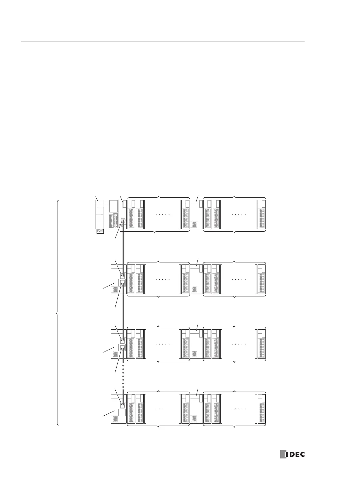
The Plus CPU module can be expanded with up to a maximum of 63 modules (I/O points: maximum 2,016 points) using expansion
interface modules (remote master/slave). The expansion interface modules (remote master/slave) are the remote master which
connects to the expansion connector of the Plus CPU module and the remote slave which connects to expansion modules that are
positioned away from the CPU module.
The expansion interface remote master module can be connected only to the basic expansion side of the Plus CPU module. At this
time, the maximum number of expansion modules (basic expansion side) that can be connected to the remote master is five
modules, but additional eight expansion modules (expansion interface side) can be connected by installing the expansion interface
module (expander).
Expansion interface remote slave modules are daisy chained to the remote master using Ethernet cables.
The group of expansion modules that are connected to the expansion connectors and communication connectors of the Plus CPU
module and expansion interface remote slave modules are called as nodes. As illustrated below, the first node that includes the
Plus CPU module is called node 0, and the nodes containing remote slaves are called node 1, node 2, and up to node 10 in order
from those closest to node 0. The maximum number of nodes is 11, from node 0 to node 10.
The maximum number of expansion modules (basic expansion side) that can be connected to the remote slaves is seven modules,
but additional eight expansion modules (expansion interface side) can be connected by installing the expansion interface module
(expander).
Expansion Interface
Remote Slave Module
(FC6A-EXM1S,
FC6A-EXM1S4)
Expansion
Modules
Daisy Chain
Connection
Plus CPU Module
Expansion Interface
Module (Expander)
(FC6A-EXM2, FC6A-EXM24)
Expansion Interface
Remote Master Module
(FC6A-EXM1M)
Expansion Interface
Remote Slave Module
(FC6A-EXM1S,
FC6A-EXM1S4)
Expansion Interface
Remote Slave Module
(FC6A-EXM1S,
FC6A-EXM1S4)
Expansion
Modules
Basic Expansion Side
Ethernet Cable
(
Length Between Nodes: 100 m max.
)
5 maximum 8 maximum
Expansion Interface Side
Expansion
Modules
Expansion Interface
Module (Expander)
(FC6A-EXM2, FC6A-EXM24)
Expansion
Modules
Basic Expansion Side
7 maximum 8 maximum
Expansion Interface Side
Expansion
Modules
Expansion Interface
Module (Expander)
(FC6A-EXM2, FC6A-EXM24)
Expansion
Modules
Basic Expansion Side
7 maximum 8 maximum
Expansion Interface Side
Expansion
Modules
Expansion Interface
Module (Expander)
(FC6A-EXM2, FC6A-EXM24)
Expansion
Modules
Basic Expansion Side
7 maximum 8 maximum
Expansion Interface Side
Node 0
Node 1
Node 2
Node 10
(1)
(2)
(3)
(4)
Expansion Port [Exp. port M]
Expansion Port 1 [Exp. port S1]
Expansion Port 2 [Exp. port S2]
Expansion Port 1 [Exp. port S1]
Expansion Port 1 [Exp. port S1]
Expansion Port 2 [Exp. port S2]

 Loading...