6: D
EVICES
6-30 FC6A S
ERIES
MICROS
MART
U
SER
’
S
M
ANUAL
FC9Y-B1722
■ D8006: User Program Execution Error Code
FC6A Series MICROSmartuser program execution error information is written to this register. When a user program execution
error occurs, the error code corresponding to the error that occurred is written to this register. For details on user program
execution errors, see "User Program Execution Error" on page 13-6.
■ D8008 to D8021: Calendar/Clock Data
D8008 through D8021 are used for reading calendar/clock data from the internal clock and for writing calendar/clock data to the
internal clock. For details on the calendar/clock data, see "Clock Function" on page 5-63.
■ D8022 to D8025: Scan Time Data
D8022 through D8025 are special data registers for checking the scan time and configuring the constant scan time. For details
on the scan time, see "Constant Scan Time" on page 5-61.
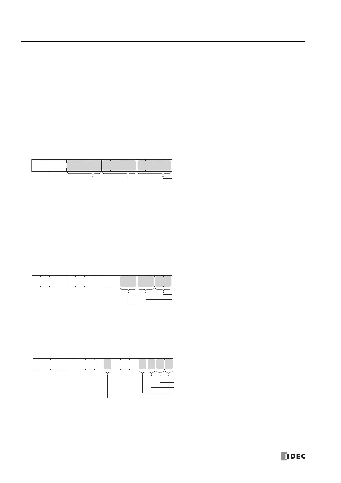
■ D8026: Communication Mode Information (Port 1 to 3)
This register indicates communication mode information for Port 1 to Port 3.
The allocation of communication ports in the device (bit assignment) is as follows.
■ D8029: System Software Version
The CPU module system software version number is written to this register.
■ D8030: Communication Cartridge Information
This register indicates information about the communication cartridges in Port 2 and Port 3.
The allocation of communication ports in the device (bit assignment) is as follows.
■ D8031: Optional Device Connection Information
Optional device connection information is written to this register.
The allocation of bits in the device (bit assignment) is as follows.
■ D8032 to D8035, D8214, D8215: Interrupt Input Jump Destination Label No.
Jump destination label numbers for interrupt inputs are written to these registers. When using interrupt inputs, write the label
number that corresponds to the special data register that has been allocated to the interrupt input. For details on interrupt
inputs, see "Interrupt Input" on page 5-37.
D8032 = I1
D8033 = I3
Bit
15
Bit
0
Bit
7
Bit
8
Bit
4
Port 1
Port 2
Port 3
Bit
3
Bit
11
0 (0000): Maintenance communication
1 (0001): User communication
2 (0010): Modbus RTU master
3 (0011): Modbus RTU slave
4 (0100): Data link communication
Bit
15
Bit
0
Bit
7
Bit
8
Bit
1
Bit
2
Bit
3
Bit
4
Bit
5
Cartridge Slot 1
Cartridge Slot 2
Cartridge Slot 3
0 (00): No communication cartridges
1 (01): RS-232C communication cartridge
2 (10): RS-485 communication cartridge
3 (11): Bluetooth communication cartridge
Bit
15
Bit
0
Bit
7
Bit
8
1
Reserved=0
SD Memory Card
2
3
Cartridge Slot 1
Cartridge Slot 2
Cartridge Slot 3
0: No optional device
1: Optional device is connected
 Loading...
