7: HMI F
UNCTION
7-36 FC6A S
ERIES
MICROS
MART
U
SER
’
S
M
ANUAL
FC9Y-B1722
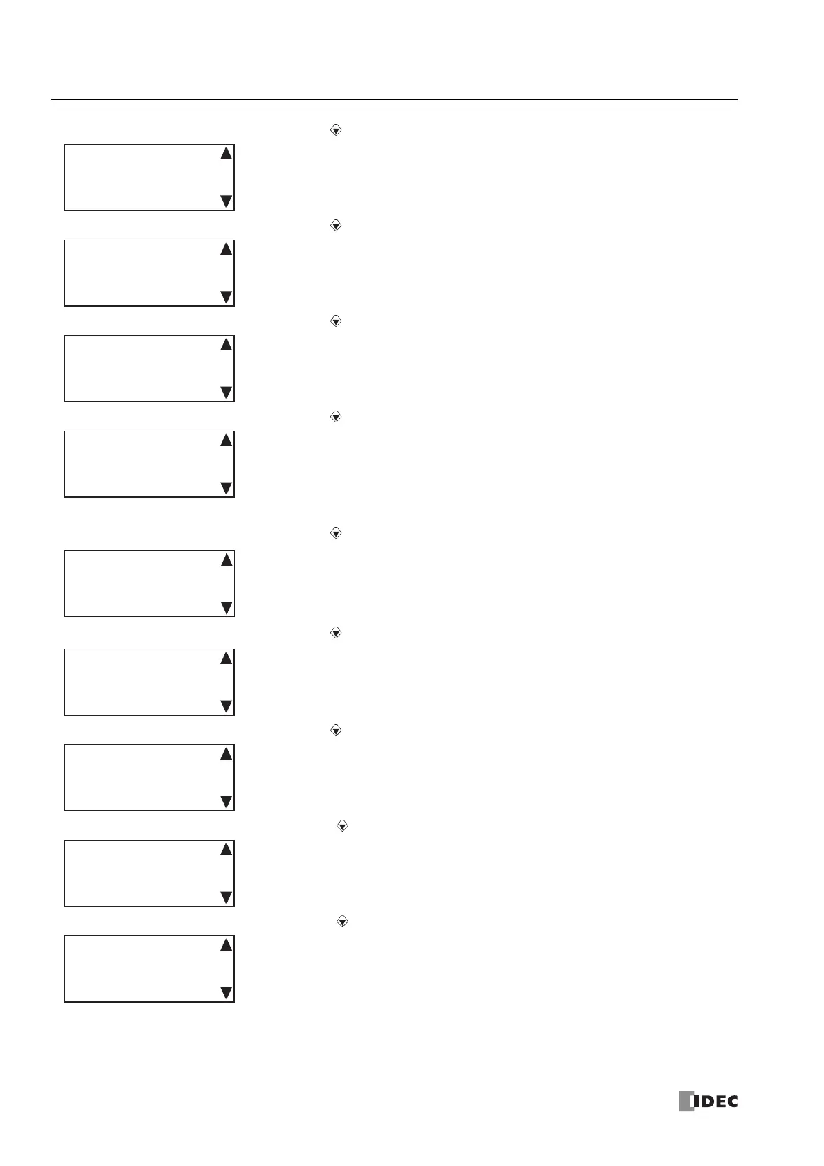
9. CPU Network Settings 3 is displayed. Press the (down) button.
10. CPU Network Settings 4 is displayed. Press the (down) button.
11. CPU Network Settings 5 is displayed. Press the (down) button.
12. CPU Network Settings 6 is displayed. Press the (down) button.
When the connected PLC is All-in-One CPU module or CAN J1939 All-in-One CPU module, the screen goes to the step 19.
13. CPU Network Settings 7 is displayed. Press the (down) button.
14. CPU Network Settings 8 is displayed. Press the (down) button.
15. CPU Network Settings 9 is displayed. Press the (down) button.
16. CPU Network Settings 10 is displayed. Press the (down) button.
17. CPU Network Settings 11 is displayed. Press the (down) button.
Default Gateway
㸸
192.168. 1. 3
CPU Network Settings 3
Preferred DNS Server:
192.168. 1.200
CPU Network Settings 4
Alternate DNS Server:
192.168. 1.201
CPU Network Settings 5
MAC Address
㸸
FF-FF-FF-FF-FF-FF
CPU Network Settings 6
Setting: Fixed
IP Address
192.168. 2. 6
CPU Network Settings 7
Subnet Mask
㸸
255.255.254. 0
CPU Network Settings 8
Default Gateway
㸸
192.168. 2. 3
CPU Network Settings 9
Preferred DNS Server:
192.168. 2.200
CPU Network Settings 10
Alternate DNS Server:
192.168. 2.201
CPU Network Settings 11

 Loading...