2: P
RODUCT
S
PECIFICATIONS
2-14 FC6A S
ERIES
MICROS
MART
U
SER
’
S
M
ANUAL
FC9Y-B1722
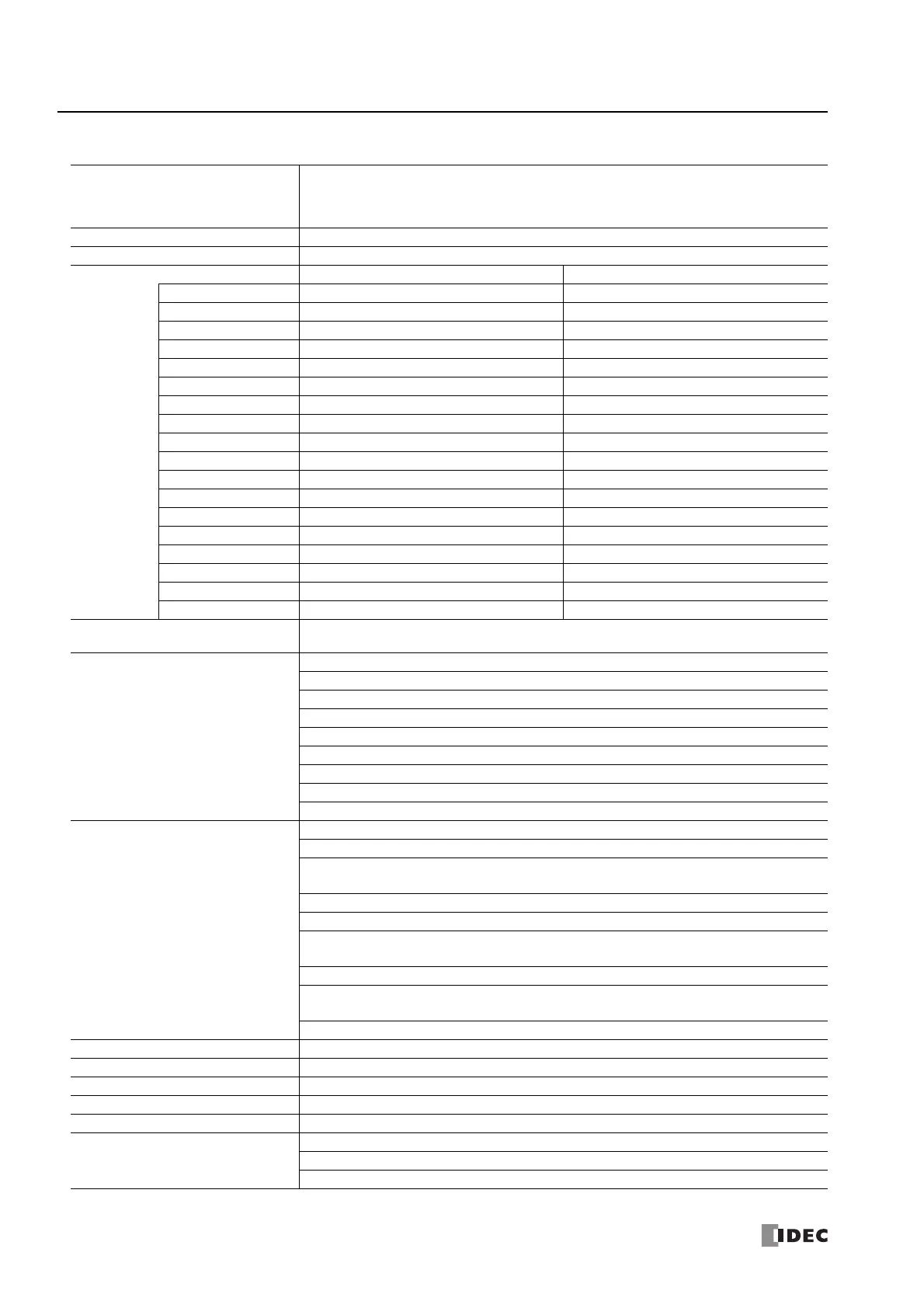
■ 12V DC Power Type
Type No.
FC6A-C16R1DE, FC6A-C16R4DE, FC6A-C16K1DE, FC6A-C16K4DE, FC6A-C16P1DE,
FC6A-C16P4DE, FC6A-C40R1DE, FC6A-C40R4DE, FC6A-C40K1DE, FC6A-C40K4DE,
FC6A-C40P1DE, FC6A-C40P4DE, FC6A-C40R1DEJ, FC6A-C40R4DEJ, FC6A-C40K1DEJ,
FC6A-C40K4DEJ, FC6A-C40P1DEJ, FC6A-C40P4DEJ
Rated Power Voltage 12V DC
Voltage Fluctuation Range 10.2 to 18V DC (including ripple)
Maximum Power Consumption Standalone When Maximum Load is Connected
FC6A-C16R1DE 3.24 W (12V DC) 12.00 W (12V DC)
FC6A-C16R4DE 3.24 W (12V DC) 12.00 W (12V DC)
FC6A-C16K1DE 3.00 W (12V DC) 12.00 W (12V DC)
FC6A-C16K4DE 3.00 W (12V DC) 12.00 W (12V DC)
FC6A-C16P1DE 3.12 W (12V DC) 12.00 W (12V DC)
FC6A-C16P4DE 3.12 W (12V DC) 12.00 W (12V DC)
FC6A-C40R1DE 4.14 W (12V DC) 23.28 W (12V DC)
FC6A-C40R4DE 4.14 W (12V DC) 23.28 W (12V DC)
FC6A-C40K1DE 3.12 W (12V DC) 23.28 W (12V DC)
FC6A-C40K4DE 3.12 W (12V DC) 23.28 W (12V DC)
FC6A-C40P1DE 3.12 W (12V DC) 23.28 W (12V DC)
FC6A-C40P4DE 3.12 W (12V DC) 23.28 W (12V DC)
FC6A-C40R1DEJ 4.08 W (12V DC) 23.28 W (12V DC)
FC6A-C40R4DEJ 4.08 W (12V DC) 23.28 W (12V DC)
FC6A-C40K1DEJ 3.84 W (12V DC) 23.28 W (12V DC)
FC6A-C40K4DEJ 3.84 W (12V DC) 23.28 W (12V DC)
FC6A-C40P1DEJ 3.84 W (12V DC) 23.28 W (12V DC)
FC6A-C40P4DEJ 3.84 W (12V DC) 23.28 W (12V DC)
Allowable Momentary Power
Interruption
10 ms or longer (when rated power supply voltage)
Withstand Voltage
Between power and FE terminals: 500V AC, 1 minute
Between input and FE terminals: 500V AC, 1 minute
Between transistor output and FE terminals: 500V AC, 1 minute
Between relay output and FE terminals: 2,300V AC, 1 minute
Between power and input terminals: 500V AC, 1 minute
Between power and transistor output terminals: 500V AC, 1 minute
Between power and relay output terminals: 2,300V AC, 1 minute
Between input and transistor output terminals: 500V AC, 1 minute
Between input and relay output terminals: 2,300V AC, 1 minute
Insulation Resistance
Between power and FE terminals: 100 MΩ or higher (500V DC insulation resistance tester)
Between input and FE terminals: 100 MΩ or higher (500V DC insulation resistance tester)
Between transistor output and FE terminals: 100 MΩ or higher (500V DC insulation resistance
tester)
Between relay output and FE terminals: 100 MΩ or higher (500V DC insulation resistance tester)
Between power and input terminals: 100 MΩ or higher (500V DC insulation resistance tester)
Between power and transistor output terminals: 100 MΩ or higher (500V DC insulation resistance
tester)
Between power and relay output terminals: 100 MΩ or higher (500V DC insulation resistance tester)
Between input and transistor output terminals: 100 MΩ or higher (500V DC insulation resistance
tester)
Between input and relay output terminals: 100 MΩ or higher (500V DC insulation resistance tester)
Inrush Current 35 A maximum
Isolation Between power terminal and internal circuit: Transformer isolated
Ground D-type ground (Class 3 ground)
Grounding Wire See "Recommended Ferrule List" on page 3-46
Power Supply Wire See "Recommended Ferrule List" on page 3-46
Effect of Improper Power Supply
Connection
Reverse polarity: Normal operation
Improper voltage or frequency: Permanent damage may be caused
Improper lead connection: Permanent damage may be caused

 Loading...