Home
IDEC
Computer Hardware
MICROSmart FC6A Series
IDEC MICROSmart FC6A Series User Manual
5
of 1
of 1 rating
662 pages
Give review
Manual
Specs
To Next Page
To Next Page
To Previous Page
To Previous Page
Loading...
FC6A S
ERIES
MICROS
MART
U
SER
’
S
M
ANUAL
FC9Y-B17
22
11-33
11: SD M
EMORY
C
ARD
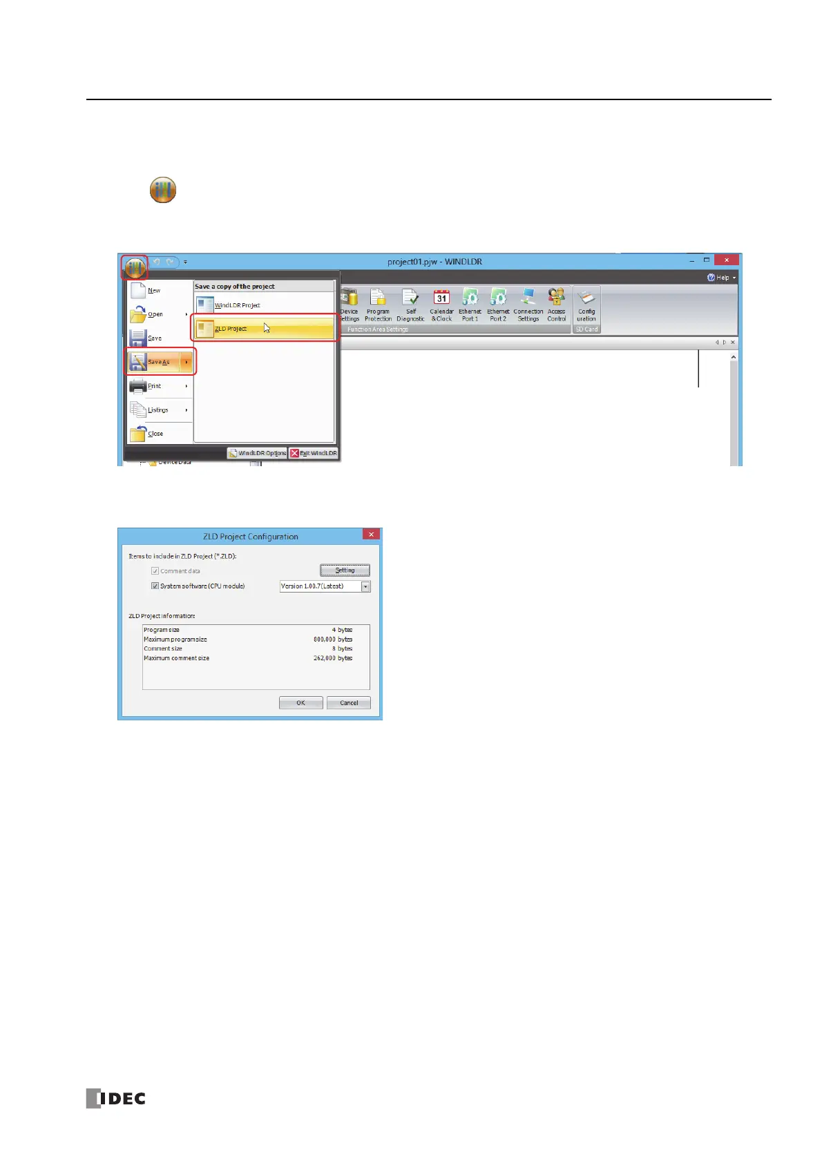
Creating a ZLD File Using WindLDR
ZLD files are created with t
he following procedur
e.
1.
Click (application)
>
Save As
>
ZLD Proje
ct
.
The
ZLD Project Co
nfiguration
dialog box is displayed.
2.
Configure the ZL
D file details.
3.
Click
OK
.
The
Save As
dialog box is displayed.
568
570
Table of Contents
Default Chapter
2
Safety Precautions
2
About this Manual
4
About the Warranty of the Products
7
Related Manuals
8
Table of Contents
11
Hapter
12
About the FC6A Series Microsmart
15
Features
22
Special Functions
23
Communication Functions
26
Maintenance Communication
28
Modbus Communication
29
User Communication
29
Data Link Communication
30
Ethernet Communication
31
Operator Interface Connectivity
32
Using J1939 Communication
32
Bacnet Communication
33
Ethernet/Ip Communication
34
MQTT Communication
35
CHAPTER 2 :Product Specifications
37
Normal Operating Conditions
37
CPU Module
40
Digital I/O Modules
105
Analog I/O Modules
141
PID Module
163
Communication Modules
173
Expansion Interface Modules
179
HMI Module
188
Cartridge Base Module
188
Cartridges
200
Dimensions
213
Rating at Max Surrounding Air Temperature of 55°C/65°C
222
Installation and Wiring
233
Installation Location
233
Assembly Methods
236
Mounting on DIN Rail
242
Input/Output Wiring
250
Power Supply and Power Supply Wiring
252
Using the Ports
256
Using an SD Memory Card
262
Replacing the Backup Battery
266
Connection Restrictions When Expanding the PLC
269
Terminal Connection
277
Wiring the CAN J1939 Bus
284
CHAPTER 4 :Operation Basics
287
Start Windldr
287
PLC Selection
288
Create Program
289
Save Project
294
Simulate Operation
295
Download Program
296
Monitor Operation
298
Exit Windldr
298
Windows Displayed in the Workspace
299
Checking the Windldr Version Number
302
Ladder Program Operation
303
Start/Stop Operation
304
CHAPTER 5 :Functions and Settings
307
Function List
307
Function Area Settings
309
Stop Input and Reset Input
311
Run/Stop Selection at Keep Data Error
315
Run/Stop Selection at Power up
316
Function Switch Configuration
317
Memory Backup
319
High-Speed Counter
321
Catch Input
341
Interrupt Input
343
Frequency Measurement
346
Input Filter
348
Analog Voltage Input
350
Analog Potentiometer
352
Timer Interrupt
354
Forced I/O Function
356
External Memory Devices
360
Log Data File Size
361
32-Bit Data Storage Setting
362
User Program Protection
364
Watchdog Timer Setting
366
Constant Scan Time
367
Daylight Savings Time
368
Clock Function
369
Battery Monitor
372
USB Boot
374
User Program Capacity
376
Online Edit
377
CHAPTER 6 :Devices
385
Device Addresses
385
Special Internal Relay
388
Special Data Register
401
HMI Function
435
HMI Function Overview
435
LCD Settings
437
About the Menu Screen
439
Basic Operations
440
Switching Run/Stop
443
Editing Programs
444
FC6A Series Microsmart Environment Settings
446
Monitoring the FC6A Series Microsmart
466
Checking/Clearing Error Information
472
Displaying Arbitrary Messages
474
SD Memory Card Maintenance
475
Reading and Writing Recipe Files
477
Uploading/Downloading the User Program
479
System Menu Hierarchy Diagram
481
Communication Functions
482
CHAPTER 8 :Instructions Reference
483
Basic Instruction List
483
Advanced Instruction List
485
Structure of an Advanced Instruction
488
Input Condition for Advanced Instructions
488
Source and Destination Devices
488
Using Timer or Counter as Source Device
488
Using Timer or Counter as Destination Device
488
Data Types for Advanced Instructions
489
Discontinuity of Device Areas
493
NOP (no Operation)
493
Device Addressing for Instruction Execution
494
Analog I/O Modules
501
Analog I/O Module Overview
501
Analog I/O Module Parameter Settings
504
Device Allocation
515
CHAPTER 10 :I/O Cartridges
523
Digital I/O Cartridge
523
Analog I/O Cartridge
529
CHAPTER 11 :SD Memory Card
537
SD Memory Card Overview
537
Save Log Data
543
Recipe Function
544
SD Memory Card Configuration Dialog Box
558
Download from SD Memory Card
563
Download a ZLD File Uploaded from the PLC (1-Time Upload)
565
Upload to SD Memory Card
579
SD Memory Card Maintenance with Data File Manager
584
Module Configuration Editor
601
Module Configuration Editor Overview
601
Basic Module Configuration Editor Operations
603
CHAPTER 13 :Troubleshooting
609
Reading Error Data
609
Special Data Registers for Error Information
611
General Error Codes
611
FC6A Series Microsmart Operating Status, Output, and ERR LED During Errors
612
Error Causes and Actions
612
User Program Execution Error
614
User Program Execution Error History
616
Troubleshooting Diagrams
618
Appendix
637
Type List
637
System Software
645
Fonts
648
Cables
650
HMI Screen Transition Diagram
652
Ppendix
637
Other manuals for IDEC MICROSmart FC6A Series
Ladder Programming Manual
604 pages
5
Based on 1 rating
Ask a question
Give review
Questions and Answers:
Need help?
Do you have a question about the IDEC MICROSmart FC6A Series and is the answer not in the manual?
Ask a question
IDEC MICROSmart FC6A Series Specifications
General
Brand
IDEC
Model
MICROSmart FC6A Series
Category
Computer Hardware
Language
English
Related product manuals
IDEC MICROSmart FC6A-C24R1CE
662 pages