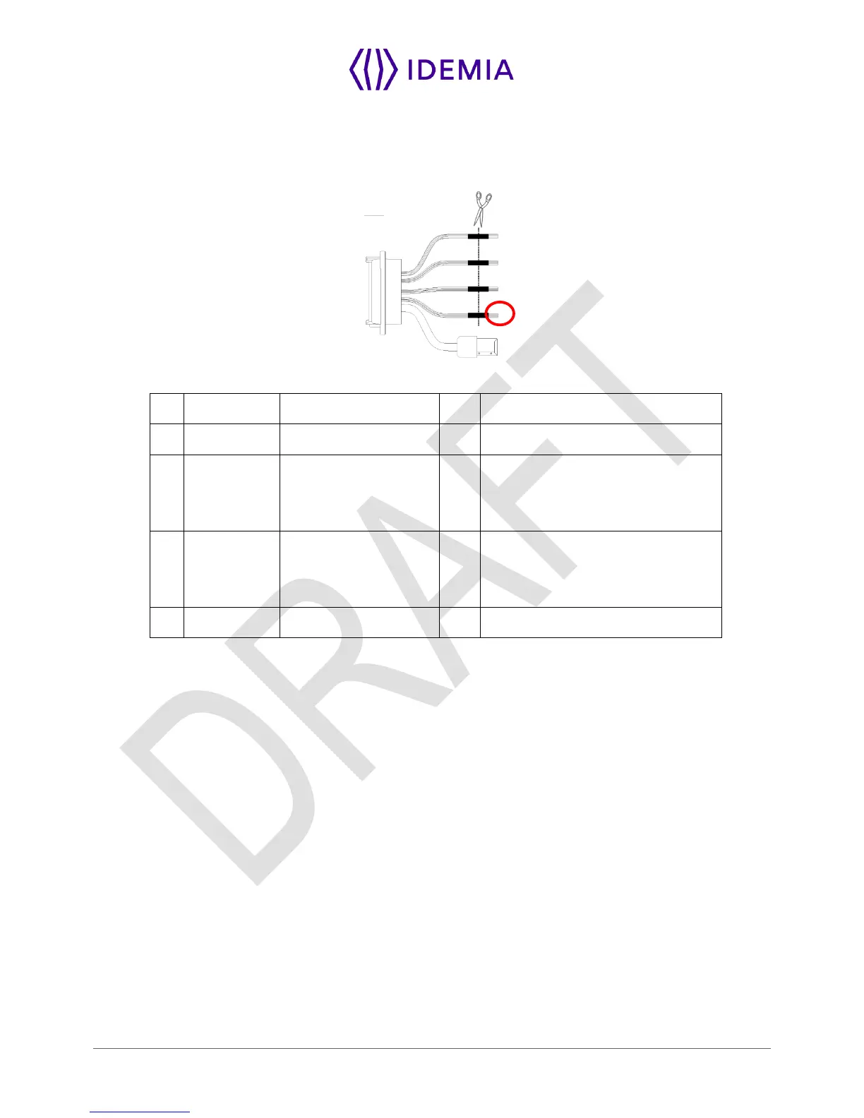
The use of LED1 and LED2 wires is described in the paragraphs below.
The controller supports neither LED1 nor LED2 signals
When the access controller has no relay contact to provide an answer to the MorphoWave Compact
terminal, then the decision to emit either the “access granted” signal or the “access denied” signal is taken
by another way. It is either the MorphoWave Compact terminal itself that decide, or it waits for the access
controller answer through the local area network (TCP), or on the serial port in (RS485 or RS422).
It is strongly recommended to disable the LED IN feature, to avoid any interference on MorphoWave
Compact terminal behavior.
The controller supports only LED1 signal
When the access controller has only one relay contact which is dedicated to the “access granted” answer,
this one must be connected between the LED1 and GND wires. The LED1 wire is set to the low level by
closing the contact between the LED1 and the GND wires, and it means “access granted”.
The MorphoWave Compact terminal uses the timeout of the wait for a low level on the on LED1 wire or
LED2 wire as “access denied” answer.
To minimize at most the waiting time of the user, the MorphoWave Compact terminal timeout value, must
be adjusted to a value a little bit higher than the maximal value of the controller response time.
Warning: if the LED2 wire is connected, it must be constantly maintained in the high state.