EasyManua.ls Logo

Idemia MorphoWave Compact - Serial Port Wiring

Idemia MorphoWave Compact
80 pages
Print Icon
To Next Page IconTo Next Page
To Previous Page IconTo Previous Page
Loading...
51
MorphoWave Compact - 2018_2000035853
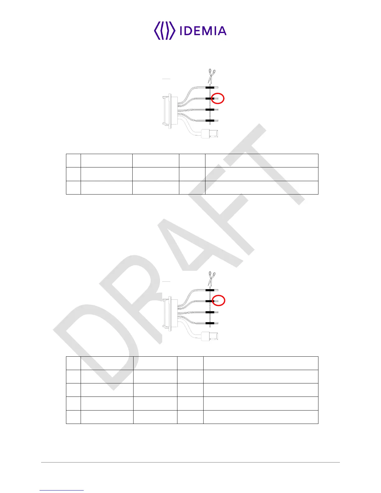
RS485
Figure 18: Serial port wiring RS485
7
Blue / Black
RS485_RX_A
In/Out
RS485 Rx/Tx non inverting signal
9
Blue / White
RS485_RX_B
In/Out
RS485 Rx/Tx inverting signal
11
Black / Red
RS485_GND
Ground
RS485 implementation is limited to half-duplex communication. So only Tx+, Tx- and ground reference
signals are necessary.
Depending on the RS485 network, an impedance adaptation may be required.
For farthest terminal, a 120-Ohms resistor termination may be added outside the terminal between TX+
and TX-.
RS422
Figure 19: Serial port wiring RS422
7
Blue / Black
RS485_RX_A
In
RS422 non inverting Receive
9
Blue / White
RS485_RX_B
In
RS422 inverting Receive
10
Green / Black
RS485_TX_Y
Out
RS422 non inverting Transmit
8
Green / White
RS485_TX_Z
Out
RS422 inverting Transmit
11
Black / Red
RS485_GND
Ground
RS422 interface is a full duplex communication.

Table of Contents

Other manuals for Idemia MorphoWave Compact

Related product manuals