0 ≤ d ≤ 255
[Description] Selects a bit-image mode using m for the number of dots specified by nL and nH,
as follows:
m
Mode
Vertical Direction Horizontal Direction
Number of
Dots
Dot
Density
Dot
Density
Number of Data
(K)
0 8-dot single-density 8 67 DPI 100 DPI
nL + nH
╳
256
1 8-dot double-density 8 67 DP 200 DPI
nL + nH
╳
256
32 24-dot single-density 24 200DPI 100 DPI
(nL + nH
╳
256)
╳
3
33 24-dot double-density 24 200 DPI 200DPI (nL + nH
╳
256)
╳
3
[dpi:dot/25.4mm{1”}]
[Details] • If the values of m is out of the specified range, nL and data following are
processed as normal data.
• The nL and nH indicate the number of dots of the bit image in the horizontal
direction. The number of dots is calculated by nL + nH
╳
256.
• If the bit-image data input exceeds the number of dots to be printed on a line,
the excess data is ignored.
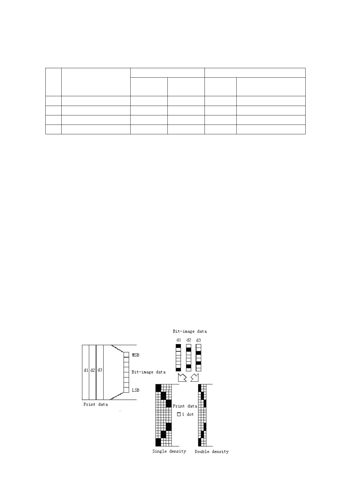
• d indicates the bit-image data. Set a corresponding bit to 1 to print a dot or to 0
• If the width of the printing area set by GS L and GS W less than the width
required by the data sent with the ESC * command, the following will be
performed on the line in question (but the printing cannot exceed the maximum
① The width of the printing area is extended to the right to accommodate the
② If step ① does not provide sufficient width for the data, the left margin is
reduced to accommodate the data.
• After printing a bit image, the printer returns to normal data processing mode.
• This command is not affected by print modes (emphasized, double-strike,
underline, character size or white/black reverse printing), except upside-down
• The relationship between the image data and the dots to be printed is as
• When 8-dot bit image is selected: